Nissan Altima (L32) 2007-2012 Service Manual: Front power window switch
Description
• BCM supplies power.
• Front power window motor RH will be operated if power window and door lock/unlock switch RH is operated.
Component Function Check
Power Window And Door Lock/unlock Switch RH
1. CHECK POWER WINDOW MOTOR FUNCTION
Does front power window motor operate with power window and door lock/unlock switch RH operation? Is the inspection result normal? YES >> Power window and door lock/unlock switch RH power supply and ground circuit are OK.
NO >> Refer to PWC-108, "FRONT POWER WINDOW SWITCH : Diagnosis Procedure".
Diagnosis Procedure
Power Window And Door Lock/Unlock Switch RH Power Supply Circuit Check
1. CHECK POWER SUPPLY CIRCUIT
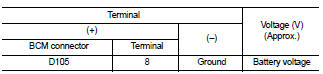
1. Turn ignition switch ON.
2. Check voltage between power window and door lock/unlock switch RH connector and ground.
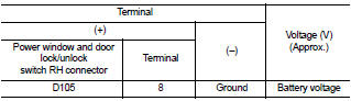
Is the measurement value within the specification? YES >> GO TO 3
NO >> GO TO 2
2. CHECK HARNESS CONTINUITY
1. Turn ignition switch OFF.
2. Disconnect BCM and power window and door lock/unlock switch RH.
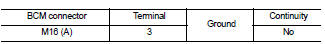
3. Check continuity between BCM connector (A) and power window and door lock/unlock switch RH connector (B).
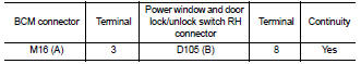
4. Check continuity between BCM connector (A) and ground.
Is the inspection result normal? YES >> GO TO 4
NO >> Repair or replace harness.
3. CHECK HARNESS CONTINUITY (POWER WINDOW AND DOOR LOCK/UNLOCK SWITCH RH)
1. Turn ignition switch OFF.
2. Disconnect main power window and door lock/unlock switch and power window and door lock/unlock switch RH.
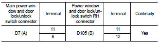
3. Check continuity between main power window and door lock/ unlock switch connector (A) and power window and door lock/ unlock switch RH connector (B).
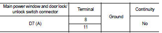
4. Check continuity between main power window and door lock/unlock switch connector (A) and ground.
Is the inspection result normal? YES >> Check intermittent incident. Refer to GI-42, "Intermittent Incident".
NO >> Repair or replace harness.
4. CHECK HARNESS CONTINUITY
1. Connect BCM.
2. Turn ignition switch ON.
3. Check voltage between power window and door lock/unlock switch RH connector and ground.
Is the inspection result normal? YES >> GO TO 5
NO >> Repair or replace harness.
5. CHECK POWER WINDOW AND DOOR LOCK/UNLOCK SWITCH RH
Check power window and door lock/unlock switch RH.
Refer to PWC-110, "FRONT POWER WINDOW SWITCH : Component Inspection".
Is the inspection result normal? YES >> Check intermittent incident. Refer to GI-42, "Intermittent Incident".
NO >> Replace power window and door lock/unlock switch RH. Refer to PWC-186, "Removal and Installation".
Component Inspection
COMPONENT INSPECTION
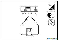
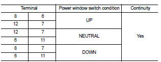
1. CHECK POWER WINDOW AND DOOR LOCK/UNLOCK SWITCH RH
Check power window and door lock/unlock switch RH.
Is the inspection result normal? YES >> Power window and door lock/unlock switch RH is OK.
NO >> Replace power window and door lock/unlock switch RH. Refer to PWC-186, "Removal and Installation".
 Power window main switch
 Rear power window switch