Nissan Altima (L32) 2007-2012 Service Manual: Fuel level sensor signal circuit
Description
The fuel level sensor unit and fuel pump detects the approximate fuel level in the fuel tank and transmits the fuel level signal to the combination meter.
Component Function Check
1.COMBINATION METER INPUT SIGNAL
1. Select “METER/M&A” on CONSULT-III.
2. Using “FUEL METER” of “DATA MONITOR”, compare the value of DATA MONITOR with fuel gauge pointer of combination meter.
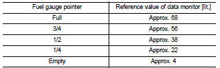
Does the data monitor value approximately match the fuel gauge indication? YES >> Inspection End.
NO >> Replace combination meter. Refer to MWI-176, "Removal and Installation".
Diagnosis Procedure
1.CHECK HARNESS CONNECTOR
1. Turn ignition switch OFF.
2. Check combination meter and fuel level sensor unit terminals (meter-side and harness-side) for poor connection.
Is the inspection result normal? YES >> GO TO 2
NO >> Repair or replace terminals or connectors.
2.CHECK FUEL LEVEL SENSOR UNIT CIRCUIT
1. Disconnect combination meter connector and fuel level sensor unit connector.
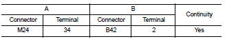
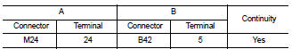
2. Check continuity between combination meter harness connector (A) and fuel level sensor unit and fuel pump harness connector (B).
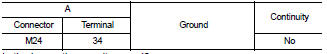
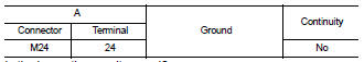
3. Check continuity between combination meter harness connector (A) and ground.
Is the inspection result normal? YES >> GO TO 3
NO >> Repair harness or connector.
3.CHECK FUEL LEVEL SENSOR UNIT GROUND CIRCUIT
1. Check continuity between combination meter harness connector (A) and fuel level sensor unit and fuel pump harness connector (B).
2. Check continuity between combination meter harness connector (A) and ground.
Is the inspection result normal? YES >> GO TO 4
NO >> Repair harness or connector.
4.CHECK INSTALLATION CONDITION
Check fuel level sensor unit installation, and check whether the float arm interferes or binds with any of the internal components in the fuel tank.
Is the inspection result normal? YES >> Inspection End.
NO >> Install the fuel level sensor unit properly.
Component Inspection
1.REMOVE FUEL LEVEL SENSOR UNIT
Remove the fuel level sensor unit. Refer to FL-6, "Removal and Installation".
>> GO TO 2
2.CHECK FUEL LEVEL SENSOR UNIT AND FUEL PUMP
Check the resistance between terminals 2 and 5.
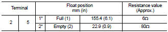
1* and 2*: When float arm is in contact with stopper.
Is inspection result normal? YES >> Inspection End.
NO >> Replace fuel level sensor unit and fuel pump. Refer to FL-6, "Removal and Installation".
 IPDM E/R (Intelligent power distribution
module engine room)
IPDM E/R (Intelligent power distribution
module engine room) Oil pressure switch signal circuit