Nissan Altima (L32) 2007-2012 Service Manual: Fuel pressure
Inspection
FUEL PRESSURE RELEASE

1. Turn ignition switch ON.
2. Perform “FUEL PRESSURE RELEASE” in “WORK SUPPORT” mode with CONSULT-III.
3. Start engine.
4. After engine stalls, crank it two or three times to release all fuel pressure.
5. Turn ignition switch OFF.

1. Remove fuel pump fuse located in IPDM E/R.
2. Start engine.
3. After engine stalls, crank it two or three times to release all fuel pressure.
4. Turn ignition switch OFF.
5. Reinstall fuel pump fuse after servicing fuel system.
FUEL PRESSURE CHECK
CAUTION: Before disconnecting fuel line, release fuel pressure from fuel line to eliminate danger.
NOTE: • Prepare pans or saucers under the disconnected fuel line because the fuel may spill out. The fuel pressure cannot be completely released because L32 models do not have fuel return system.
• Use fuel pressure gauge kit [SST: (J-44321)] to check fuel pressure.
1. Release fuel pressure to zero.
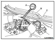
2. Connect fuel tube (B) adapter to quick connector.
A : Fuel pressure gauge
C : Fuel feed hose
3. Turn ignition switch ON and check for fuel leakage.
4. Start engine and check for fuel leakage.
5. Read the indication of fuel pressure gauge.
At idling : Approximately 350 kPa (3.57 kg/cm2, 51 psi)
6. If result is unsatisfactory, check fuel hoses and fuel tubes for clogging.
If OK, Replace “fuel filter and fuel pump assembly”.
If NG, Repair or replace.
 On-vehicle maintenance
 Evap leak check