Nissan Altima (L32) 2007-2012 Service Manual: Fuel tank
Exploded View
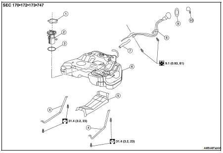
1. Lock ring
2. Fuel level sensor, fuel filter, and fuel pump assembly
3. Seal ring
4. Fuel tank mounting straps
5. Fuel tank protector
6. Fuel tank
7. Fuel filler hose
8. Fuel filler hose
9. Grommet
10. Fuel filler cap
Removal and Installation
REMOVAL
WARNING: Read “General Precautions” before working on the fuel system.
Refer to FL-4, "General Precaution".
1. Disconnect the battery negative terminal.
2. Check the fuel level with the vehicle on a level surface. If the fuel gauge indicates more than the level as shown (7/8 full), drain the fuel from the fuel tank until the fuel gauge indicates a level at or below as shown (7/8 full).
• In case the fuel pump does not operate, use the following procedure.
a. Insert fuel tubing of less than 25mm (0.98in) diameter into the fuel filler tube through the fuel filler opening to drain fuel from the fuel filler tube.
b. Disconnect the fuel filler hose from the fuel filler tube.
c. Insert fuel tubing into the fuel tank through the fuel filler hose to drain fuel from the fuel tank.
• As a guide, the fuel level reaches or is less than the level on the fuel gauge as shown, when approximately 10 (2 5/8 US gal, 2 1/4 Imp gal) of fuel is drained from a full fuel tank.
3. Open the fuel filler cap to release the pressure inside the fuel tank.
4. Release fuel pressure from fuel line, Refer to EC-550, "Inspection" (QR25DE for California), EC-1038, "Inspection" (except for California), EC-1579, "Inspection" (VQ35DE).
5. Remove rear seat bottom. For Coupe Refer to SE-25, "Removal and Installation", For Sedan Refer to SE- 53, "Removal and Installation" 6. Turn the four retainers 90° in a clockwise direction and remove the fuel pump inspection hole cover.
7. Disconnect the fuel level sensor, fuel filter, and fuel pump assembly electrical connector, EVAP hose quick connector, and fuel feed hose quick connector.
a. Disconnect the quick connectors as follows: • Hold the sides of the connector, push in tabs and pull out the tube.
• If the connector and the tube are stuck together, push and pull several times until they start to move. Then disconnect them by pulling.
CAUTION: • The tube can be removed when the tabs are completely depressed. Do not twist it more than necessary.
• Do not use any tools to remove the quick connector.
• Keep the resin tube away from heat. Be especially careful when welding near the tube.
• Prevent acid liquid such as battery electrolyte, from getting on the resin tube.
• Do not bend or twist the tube during installation and removal.
• Only when the tube is replaced, remove the remaining retainer on the tube or fuel level sensor, fuel filter, and fuel pump assembly.
• When the tube or fuel level sensor, fuel filter, and fuel pump assembly is replaced, also replace the retainer with a new one (green colored retainer).
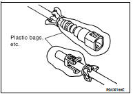
• To keep the connecting portion clean and to avoid damage and foreign materials, cover them completely with plastic bags or something similar.
8. Remove the center exhaust tube, with muffler(s). Refer to EC-1038, "Inspection" (QR25DE), EC-1579, "Inspection" (VQ35DE).
9. Disconnect the fuel filler hose and the recirculation hose at the fuel tank side.
10. Disconnect the three parking brake cable mounting brackets on each cable and position the cables out of the way. Refer to PB-6, "PEDAL TYPE : Removal and Installation"(pedal), PB-8, "LEVER TYPE : Removal and Installation"(lever).
11. Remove the fuel tank protector.
12. Disconnect the fuel tank mounting straps while supporting the fuel tank.
13. Remove the fuel tank.
14. If replacing the fuel tank, remove the fuel level sensor, fuel filter and fuel pump assembly to transfer to the new fuel tank.
INSTALLATION
Install in the reverse order of removal paying attention to the following.
• Before tightening the fuel tank mounting straps, temporarily install the filler hose and the recirculation hose.
Tighten all fuel tank mounting strap bolts to specification, then tighten the hose clamps.
• Connect the quick connector as follows: - Check the connection for damage or any foreign materials.
- Align the connector with the tube, then insert the connector straight into the tube until a click is heard.
• After the tube is connected, make sure the connection is secure by performing the following checks: - Pull on the tube and the connector to make sure they are securely connected.
- Visually confirm that the two retainer tabs are connected to the quick connector.
INSPECTION AFTER INSTALLATION
Use the following procedure to check for fuel leaks.
1. Turn the ignition switch ON (without starting the engine). Then check the connections for fuel leaks by applying fuel pressure to the fuel piping.
2. Run the engine and check for fuel leaks at the fuel system tube and hose connections.
Inspection
INSPECTION AFTER INSTALLATION
Use the following procedure to check for fuel leaks.
1. Turn ignition switch “ON” (with engine stopped), and check connections for leakage by applying fuel pressure to fuel piping.
2. Start engine and rev it up and make sure there are no fuel leaks at the fuel system tube and hose connections.
 Fuel level sensor unit, fuel filter
and fuel pump assembly
Fuel level sensor unit, fuel filter
and fuel pump assembly Service data and specifications
(SDS)
Service data and specifications
(SDS)