Nissan Altima (L32) 2007-2012 Service Manual: Function information
Component Part Location
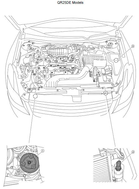
ENGINE COMPARTMENT
1. A/C compressor F3
2. Refrigerant pressure sensor E219
3. A/C relay (internal to IPDM E/R)
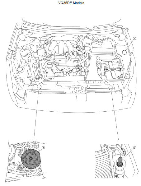
1. A/C compressor F3
2. Refrigerant pressure sensor E219
3. A/C relay (internal to IPDM E/R)
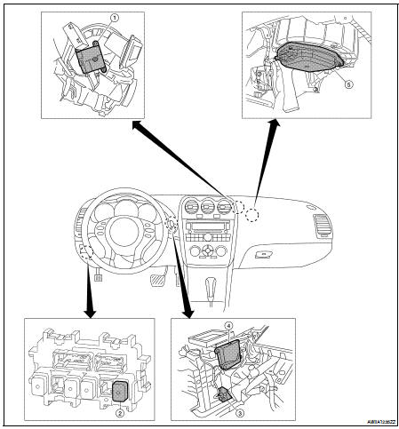
PASSENGER COMPARTMENT
1. Intake door motor M126
2. Front blower motor relay J-4
3. Air mix door motor M130
4. Mode door motor M127
5. Blower motor M31
Component’s Role
System Diagram
CONTROL SYSTEM
The control system consists of input sensors, switches, front air control and
outputs. The relationship of these
components is shown in the figure below:
System ...
Other materials: How to use the vehicle information
display
The vehicle information display can be
changed using the ,
, and OK buttons located on the
steering
wheel.
- Use these buttons
to navigate the vehicle information
display.
OK - Change or select an item in the
vehicle information display.
- Returns to the previous
menu.
The OK, a ...
Vehicle information display warnings
and indicators
The following messages may appear in
your vehicle information display.
Place the key near the start
switch
This indicator appears when the battery of
the Intelligent Key is low and when the Intelligent
Key system and the vehicle are not
communicating normally.
If this appears, touch the ignition s ...
Vehicle information display warnings
and indicators
The following messages may appear in
your vehicle information display.
Engine start operation for
Intelligent Key system (if
I-Key battery level is low)
This indicator appears when the battery of
the Intelligent Key is low and when the Intelligent
Key system and the vehicle are not
communicating no ...
 Function diagnosis
 Air conditioner control