Nissan Altima (L32) 2007-2012 Service Manual: Horn
Description
Horn (high/low) is located inside of front bumper and operates when theft warning system is in alarm phase.
Component Function Check
1.CHECK FUNCTION
1. Select HORN in “ACTIVE TEST” mode with CONSULT-III.
2. Check the horn (high/low) operation.

Is the operation normal? YES >> Inspection End.
NO >> Refer to SEC-319, "Diagnosis Procedure".
Diagnosis Procedure
1.CHECK HORN FUNCTION
Check horn function with horn switch Do the horns sound? YES >> GO TO 2
NO >> Refer to HRN-7, "Wiring Diagram - Sedan".
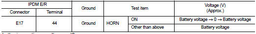
2.CHECK HORN RELAY POWER SUPPLY
1. Turn ignition switch ON.
2. Perform “ACTIVE TEST” (“HORN”) with CONSULT-Ill.
3. Using an analog voltmeter or an oscilloscope, check voltage between IPDM E/R connector E17 terminal 44 and ground.
Is the inspection result normal? YES >> Repair or replace harness between IPDM E/R and horn relay.
NO >> GO TO 3
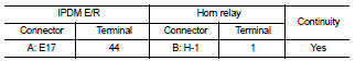
3.CHECK HORN RELAY CIRCUIT
1. Turn ignition switch OFF.
2. Disconnect IPDM E/R and horn relay connector.
3. Check continuity between IPDM E/R harness connector and horn relay harness connector.
4. Check continuity between IPDM E/R harness connector and ground.
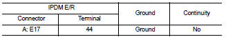
Is the inspection result normal? YES >> GO TO 4
NO >> Repair or replace harness.
4.CHECK INTERMITTENT INCIDENT
Refer to GI-42, "Intermittent Incident".
Is the inspection result normal? YES >> Replace IPDM E/R.Refer to PCS-48, "Removal and Installation".
NO >> Repair or replace the malfunctioning part.
 Key cylinder switch
 Headlamp