Nissan Altima (L32) 2007-2012 Service Manual: Ignition signal
Description
The ignition signal from the ECM is sent to and amplified by the power transistor. The power transistor turns ON and OFF the ignition coil primary circuit. This ON/OFF operation induces the proper high voltage in the coil secondary circuit.
Component Function Check
1.INSPECTION START
Turn ignition switch OFF, and restart engine.
Does the engine start? YES-1 >> With CONSULT-III: GO TO 2.
YES-2 >> Without CONSULT-III: GO TO 3.
NO >> Go to EC-963, "Diagnosis Procedure".
2.IGNITION SIGNAL FUNCTION

1. Perform “POWER BALANCE” in “ACTIVE TEST” mode with CONSULT-III.
2. Make sure that each circuit produces a momentary engine speed drop.
Is the inspection result normal? YES >> INSPECTION END
NO >> Go to EC-963, "Diagnosis Procedure".
3.IGNITION SIGNAL FUNCTION

1. Let engine idle.
2. Read the voltage signal between ECM harness connector and ground.
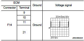
NOTE: The pulse cycle changes depending on rpm at idle.
Is the inspection result normal? YES >> INSPECTION END
NO >> Go to EC-963, "Diagnosis Procedure".
Diagnosis Procedure
1.CHECK IGNITION COIL POWER SUPPLY CIRCUIT-I
1. Turn ignition switch OFF, wait at least 10 seconds and then turn ON.
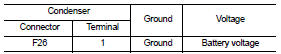
2. Check the voltage between ECM harness connector and ground.
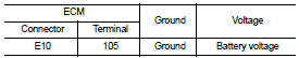
Is the inspection result normal? YES >> GO TO 2.
NO >> Go to EC-673, "Diagnosis Procedure".
2.CHECK IGNITION COIL POWER SUPPLY CIRCUIT-II
1. Turn ignition switch OFF.
2. Disconnect condenser-2 harness connector.
3. Turn ignition switch ON.
4. Check the voltage between condenser-2 harness connector and ground.
Is the inspection result normal? YES >> GO TO 4.
NO >> GO TO 3.
3.CHECK IGNITION COIL POWER SUPPLY CIRCUIT-III
1. Turn ignition switch OFF.
2. Disconnect IPDM E/R harness connector F10.
3. Check the continuity between IPDM E/R harness connector and condenser-2 harness connector.
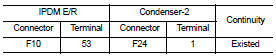
4. Also check harness for short to ground and short to power.
Is the inspection result normal? YES >> Go to EC-673, "Diagnosis Procedure".
NO >> Repair open circuit or short to ground or short to power in harness or connectors.
4.CHECK CONDENSER-2 GROUND CIRCUIT FOR OPEN AND SHORT
1. Turn ignition switch OFF.
2. Check the continuity between condenser-2 harness connector and ground.
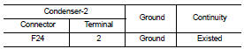
3. Also check harness for short to power.
Is the inspection result normal? YES >> GO TO 5.
NO >> Repair open circuit or short to ground or short to power in harness or connectors.
5.CHECK CONDENSER
Refer to EC-967, "Component Inspection (Condenser-2)" Is the inspection result normal?
YES >> GO TO 6.
NO >> Replace condenser.
6.CHECK IGNITION COIL POWER SUPPLY CIRCUIT-V
1. Reconnect all harness connectors disconnected.
2. Disconnect ignition coil harness connector.
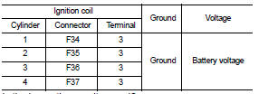
3. Turn ignition switch ON.
4. Check the voltage between ignition coil harness connector and ground.
Is the inspection result normal? YES >> GO TO 7.
NO >> Repair open circuit or short to ground or short to power in harness or connectors.
7.CHECK IGNITION COIL GROUND CIRCUIT FOR OPEN AND SHORT
1. Turn ignition switch OFF.
2. Check the continuity between ignition coil harness connector and ground.
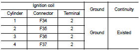
3. Also check harness for short to power.
Is the inspection result normal? YES >> GO TO 8.
NO >> Repair open circuit or short to ground or short to power in harness or connectors.
8.CHECK IGNITION COIL OUTPUT SIGNAL CIRCUIT FOR OPEN AND SHORT
1. Disconnect ECM harness connector.
2. Check the continuity between ECM harness connector and ignition coil harness connector.
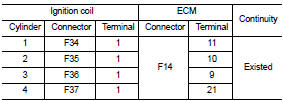
3. Also check harness for short to ground and short to power.
Is the inspection result normal? YES >> GO TO 9.
NO >> Repair open circuit or short to ground or short to power in harness or connectors.
9.CHECK IGNITION COIL WITH POWER TRANSISTOR
Refer to EC-966, "Component Inspection (Ignition Coil with Power Transistor)".
Is the inspection result normal? YES >> GO TO 10.
NO >> Replace malfunctioning ignition coil with power transistor.
10.CHECK INTERMITTENT INCIDENT
Refer to GI-42, "Intermittent Incident".
>> INSPECTION END
Component Inspection (Ignition Coil with Power Transistor)
1.CHECK IGNITION COIL WITH POWER TRANSISTOR-I
1. Turn ignition switch OFF.
2. Disconnect ignition coil harness connector.
3. Check resistance between ignition coil terminals as follows.
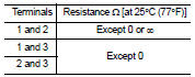
Is the inspection result normal? YES >> GO TO 2.
NO >> Replace malfunctioning ignition coil with power transistor.
2.CHECK IGNITION COIL WITH POWER TRANSISTOR-II
CAUTION: Do the following procedure in the place where ventilation is good without the combustible.
1. Turn ignition switch OFF.
2. Reconnect all harness connectors disconnected.
3. Remove fuel pump fuse in IPDM E/R to release fuel pressure.
NOTE: Do not use CONSULT-III to release fuel pressure, or fuel pressure applies again during the following procedure.
4. Start engine.
5. After engine stalls, crank it two or three times to release all fuel pressure.
6. Turn ignition switch OFF.
7. Remove all ignition coil harness connectors to avoid the electrical discharge from the ignition coils.
8. Remove ignition coil and spark plug of the cylinder to be checked.
9. Crank engine for 5 seconds or more to remove combustion gas in the cylinder.
10. Connect spark plug and harness connector to ignition coil.
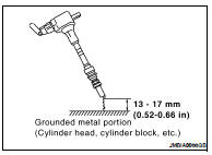
11. Fix ignition coil using a rope etc. with gap of 13 - 17 mm (0.52 - 0.66 in) between the edge of the spark plug and grounded metal portion as shown in the figure.
12. Crank engine for about three seconds, and check whether spark is generated between the spark plug and the grounded metal portion.
Spark should be generated.
CAUTION: • Do not approach to the spark plug and the ignition coil within 50 cm (19.7 in). Be careful not to get an electrical shock while checking, because the electrical discharge voltage becomes 20kV or more.
• It might cause to damage the ignition coil if the gap of more than 17 mm (0.66 in) is taken.
NOTE:
When the gap is less than 13 mm (0.52 in), the spark might be generated even if the coil is malfunctioning.
Is the inspection result normal? YES >> INSPECTION END
NO >> Replace malfunctioning ignition coil with power transistor.
Component Inspection (Condenser-2)
1.CHECK CONDENSER-2
1. Turn ignition switch OFF.
2. Disconnect condenser-2 harness connector.
3. Check resistance between condenser-2 terminals as follows.
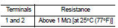
Is the inspection result normal? YES >> INSPECTION END
NO >> Replace condenser-2.
 Fuel pump
 Malfunction indicator lamp