Nissan Altima (L32) 2007-2012 Service Manual: Insufficient cooling
Component Function Check
SYMPTOM: Insufficient cooling
INSPECTION FLOW
1. CONFIRM SYMPTOM BY PERFORMING OPERATION CHECK - TEMPERATURE DECREASE
1. Press the AUTO switch.
2. Turn temperature control dial (LH) counterclockwise until 18°C (32°F) is displayed.
3. Check for cold air at discharge air outlets.
Can a symptom be duplicated? YES >> GO TO 3
NO >> GO TO 2
2. CHECK FOR ANY SYMPTOMS
Perform a complete operational check and check for any symptoms. Refer to HAC-5, "Description and Conditions".
Does another symptom exist? YES >> Refer to HAC-83, "Symptom Matrix Chart".
NO >> System OK.
3. CHECK FOR SERVICE BULLETINS
Check for any service bulletins.
>> GO TO 4
4. CHECK DRIVE BELTS
Check compressor belt tension. Refer to EM-16, "Checking Drive Belts" (QR25DE) or EM-121, "Checking Drive Belts" (VQ35DE).
Is the inspection result normal? YES >> GO TO 5
NO >> Adjust or replace A/C compressor belt. Refer to EM-16, "Removal and Installation" (QR25DE) or EM-121, "Removal and Installation" (VQ35DE).
5. CHECK AIR MIX DOOR MOTOR OPERATION
Check and verify air mix door mechanism for smooth operation.
Does air mix door operate correctly? YES >> GO TO 6
NO >> Repair or replace air mix door control linkage.
6. CHECK COOLING FAN MOTOR OPERATION
Check and verify cooling fan motor for smooth operation.
Does cooling fan motor operation correctly? YES >> GO TO 7
NO >> Check cooling fan motor. Refer to EC-949, "Component Function Check" (QR25DE) or EC-1473, "Component Function Check" (VQ35DE).
7. CHECK RECOVERY/RECYCLING EQUIPMENT BEFORE USAGE
Check recovery/recycling equipment before connecting to vehicle. Verify there is no pressure in the recovery/ recycling equipment by checking the gauges. If pressure exists, recover refrigerant from equipment lines.
>> GO TO 8
8. CHECK REFRIGERANT PURITY
1. Connect recovery/recycling equipment to vehicle.
2. Confirm refrigerant purity in supply tank using recovery/recycling and refrigerant indentifier.
Is the inspection result normal? YES >> GO TO 9
NO >> Check contaminated refrigerant. Refer to HA-24, "HFC-134a (R-134a) Service Procedure".
9. CHECK REFRIGERANT PRESSURE
Check refrigerant pressure with manifold gauge connected. Refer to HAC-88, "Trouble Diagnosis For Abnormal Pressure".
Is the inspection result normal? YES >> Perform diagnostic work flow. Refer to HAC-85, "Diagnostic Work Flow".
NO >> GO TO 10
10. CHECK FOR EVAPORATOR FREEZE UP
Start engine and run A/C. Check for evaporator freeze up.
Does evaporator freeze up? YES >> Perform diagnostic work flow. Refer HAC-85, "Diagnostic Work Flow".
NO >> GO TO 11
11. CHECK AIR DUCTS
Check ducts for air leaks.
Is the inspection result normal? YES >> System OK.
NO >> Repair air leaks.
Diagnostic Work Flow
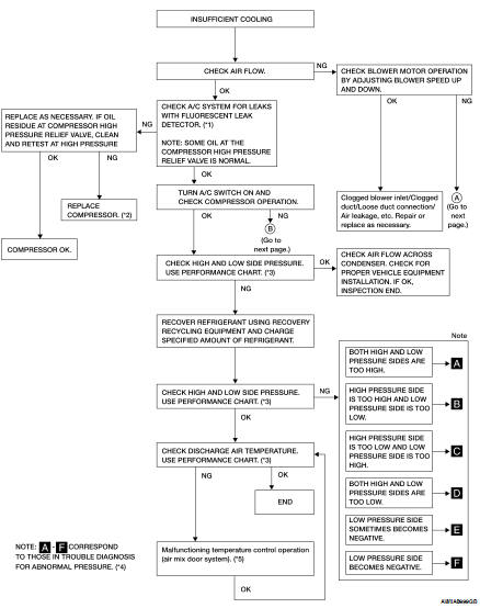
*1 HA-27, "Checking System for Leaks Using the Fluorescent Leak Detector"
*2 HA-35, "Removal and Installation for Compressor - QR25DE Models" or HA-36, "Removal and Installation for Compressor - VQ35DE Models"
*3 HAC-87, "Performance Chart"
*4 HAC-88, "Trouble Diagnosis For Abnormal Pressure"
*5 HAC-35, "Diagnosis Procedure"
*1 VTL-15, "Removal and Installation"
*2 HAC-42, "Diagnosis Procedure"
*3 HAC-47, "Diagnosis Procedure"
*4 EM-16, "Checking Drive Belts" (QR25DE) or EM-121, "Checking Drive Belts" (VQ35DE)
*5 HA-35, "Removal and Installation for Compressor - QR25DE Models" or HA-36, "Removal and Installation for Compressor - VQ35DE Models"
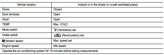
Performance Chart
TEST CONDITION
Testing must be performed as follows:
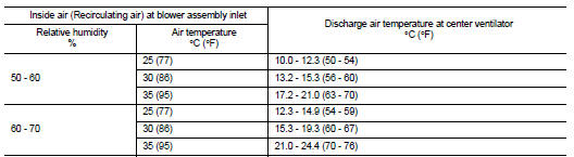
TEST READING
Recirculating-to-discharge Air Temperature Table
Ambient Air Temperature-to-operating Pressure Table
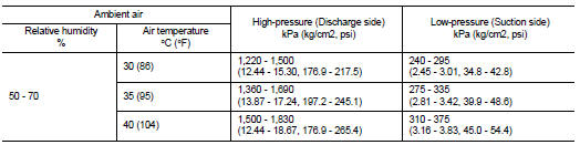
Trouble Diagnosis For Abnormal Pressure
Whenever system's high and/or low side pressure is abnormal, diagnose using a manifold gauge. The marker above the gauge scale in the following tables indicates the standard (normal) pressure range. Since the standard (normal) pressure differs from vehicle to vehicle, refer to Ambient Air Temperature-to-operating Pressure Table above.
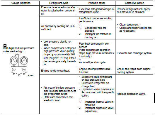
Both High- and Low-pressure Sides are Too High
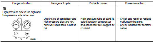
High-pressure Side is Too High and Low-pressure Side is Too Low
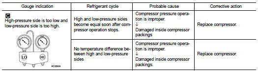
High-pressure Side is Too Low and Low-pressure Side is Too High
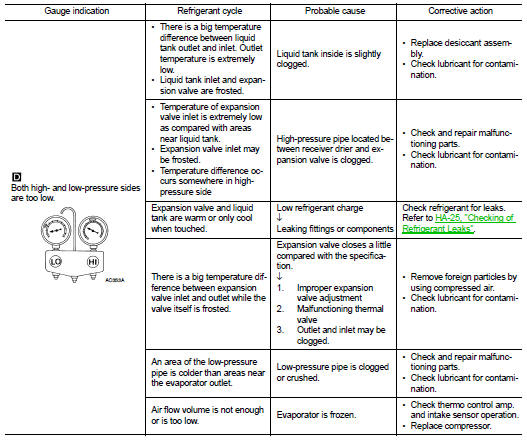
Both High- and Low-pressure Sides are Too Low
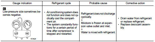
Low-pressure Side Sometimes Becomes Negative
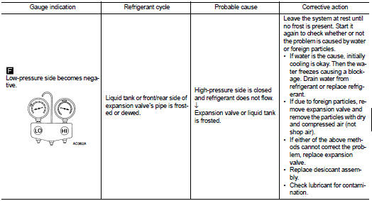
Low-pressure Side Becomes Negative
 Air conditioner control
 Insufficient heating