Nissan Altima (L32) 2007-2012 Service Manual: IPDM-E branch line circuit
Diagnosis Procedure
INSPECTION PROCEDURE
1.CHECK CONNECTOR
1. Turn the ignition switch OFF.
2. Disconnect the battery cable from the negative terminal.
3. Check the terminals and connectors of the IPDM E/R for damage, bend and loose
connection (unit side
and connector side).
Is the inspection result normal?
YES >> GO TO 2.
NO >> Repair the terminal and connector.
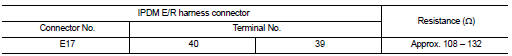
2.CHECK HARNESS FOR OPEN CIRCUIT
1. Disconnect the connector of IPDM E/R.
2. Check the resistance between the IPDM E/R harness connector terminals.
Is the measurement value within the specification?
YES >> GO TO 3.
NO >> Repair the IPDM E/R branch line.
3.CHECK POWER SUPPLY AND GROUND CIRCUIT
Check the power supply and the ground circuit of the IPDM E/R. Refer to
PCS-23, "Diagnosis Procedure" .
Is the inspection result normal?
YES (Present error)>>Replace the IPDM E/R. Refer to PCS-48, "Removal and
Installation".
YES (Past error)>>Error was detected in the IPDM E/R branch line.
NO >> Repair the power supply and the ground circuit.
Diagnosis Procedure
INSPECTION PROCEDURE
1.CHECK CONNECTOR
1. Turn the ignition switch OFF.
2. Disconnect the battery cable from the negative terminal.
3. Check the following terminals and co ...
Diagnosis Procedure
INSPECTION PROCEDURE
1.CONNECTOR INSPECTION
1. Turn the ignition switch OFF.
2. Disconnect the battery cable from the negative terminal.
3. Disconnect all the unit connect ...
Other materials: RCTA system operation
For vehicles with the 7 inch (18 cm) display
Side BSW/RCTA Indicator Light
The RCTA system can help alert the driver
of an approaching vehicle when the driver
is backing out of a parking space.
For vehicles with the 5 inch (13 cm) display
When the shift position is in R (Reverse) and
the vehicl ...
Automatic brake hold (if so equipped)
The automatic brake hold function maintains
the braking force without the driver
having to depress the brake pedal when
the vehicle is stopped at a traffic light or
intersection. As soon as the driver depresses
the accelerator pedal again, the
automatic brake hold function is deactivated
and the bra ...
Recommended fluids/lubricants and
capacities
The following are approximate capacities. The actual refill capacities may
be slightly different. When refilling, follow the procedure
described in the "Do-it-yourself" section to determine the proper refill
capacity.
...
 TCM branch line circuit
 Can communication circuit