Nissan Altima (L32) 2007-2012 Service Manual: Lan system circuit
Description
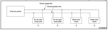
SYMPTOM: Mode door motor, intake door motor and/or air mix door motor does not operate normally.
Diagnosis Procedure
DIAGNOSIS PROCEDURE FOR LAN CIRCUIT
1.CHECK POWER SUPPLY FOR DOOR MOTORS
1. Press ignition switch ON.
2. Check voltage between front air control connector M37 terminal 20 and ground.
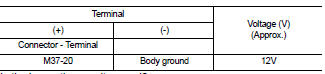
Is the inspection result normal? YES >> GO TO 2
NO >> Replace front air control. Refer to VTL-8, "Removal and Installation".
2.CHECK SIGNAL FOR DOOR MOTORS
Check voltage between front air control connector M37 terminal 3 and ground.
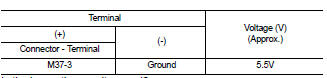
Is the inspection result normal? YES >> GO TO 3
NO >> Replace front air control. Refer to VTL-8, "Removal and Installation".
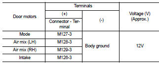
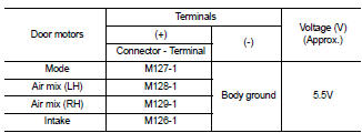
3.CHECK POWER SUPPLY FOR MOTOR
Check voltage between mode door motor connector M127 terminal 3 and ground, between air mix door motor (LH) connector M128 terminal 3 and ground, between air mix door motor (RH) connector M129 terminal 3 and ground, and between intake door motor connector M126 terminal 3 and ground.
Is the inspection result normal? YES >> GO TO 4 NO >> Replace harness or connector.
4.CHECK SIGNAL FOR MOTOR
Check voltage between mode door motor connector M127 terminal 1 and ground, between air mix door motor (LH) connector M128 terminal 1 and ground, between air mix door motor (RH) connector M129 terminal 1 and ground, and between intake door motor connector M58 terminal 1 and ground.
Is the inspection result normal? YES >> GO TO 5
NO >> Replace harness or connector.
5.CHECK MOTOR GROUND CIRCUIT
1. Press ignition switch OFF.
2. Disconnect door motor connectors.
3. Check continuity between mode door motor connector M127 terminal 2 and ground, between air mix door motor (LH) connector M128 terminal 2 and ground, between air mix door motor (RH) connector M129 terminal 2 and ground, and between intake door motor connector M126 terminal 2 and ground.
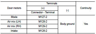
Is the inspection result normal? YES >> GO TO 6 NO >> Replace harness or connector.
6.CHECK MOTOR OPERATION
Disconnect and reconnect the motor connectors and confirm the motor operation.
Is the inspection result normal? YES >> (Returns to normal operation.) • Motor connector contacts dirty or damaged NO >> (Does not operate normally.) • GO TO 7
7.CHECK MODE DOOR MOTOR AND AIR MIX DOOR MOTORS OPERATION
1. Disconnect the intake door motor connector.
2. Reconnect the mode door motor connector and air mix door motor connectors, confirm the mode door motor and air mix door motors operation.
Is the inspection result normal? YES >> (Mode door motor and air mix door motors operate normally.) • Replace the intake door motor. refer to VTL-17, "Removal and Installation".
NO >> (Mode door motor and air mix door motor do not operate normally.) • GO TO 8
8.CHECK AIR MIX DOOR MOTOR AND INTAKE DOOR MOTOR OPERATION
1. Disconnect mode door motor connector.
2. Reconnect the intake door motor connector, confirm the air mix door motors and intake door motor operation.
Is the inspection result normal? YES >> (Air mix door motors and intake door motor operate normally.) • Replace mode door motor. Refer to VTL-18, "Removal and Installation".
NO >> (Air mix door motors and intake door motor do not operate normally.) • GO TO 9
9.CHECK INTAKE DOOR MOTOR AND MODE DOOR MOTOR OPERATION
1. Disconnect air mix door motor connectors.
2. Reconnect mode door motor connector, confirm the intake door motor and mode door motor operation.
Is the inspection result normal? YES >> (Intake door motor and mode door motor operate normally.) • Replace inoperative air mix door motor. Refer to VTL-19, "Removal and Installation".
NO >> (Intake door motor and mode door motor do not operate normally.) • Replace front air control. Refer to VTL-8, "Removal and Installation".
 Component diagnosis
 Mode door motor