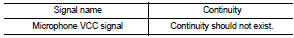
Nissan Altima (L32) 2007-2012 Service Manual: Microphone
Diagnosis Procedure
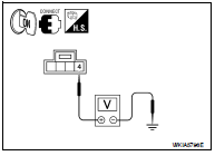
1.CHECK POWER SUPPLY CIRCUIT (MICROPHONE SIDE)
Check voltage between microphone harness connector and ground.
Is proper voltage present?
YES >> GO TO 4
NO >> GO TO 2
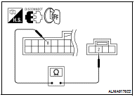
2.CHECK POWER SUPPLY CIRCUIT (CONTINUITY)
1. Turn ignition switch OFF.
2. Disconnect Bluetooth control unit and microphone connectors.
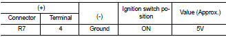
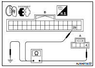
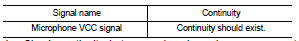
3. Check continuity between microphone harness connector R7
(A) terminal 4 and Bluetooth control unit harness connector
B126 (B) terminal 29.
4. Check continuity between microphone harness connector R7
(A) terminal 4 and ground.
Are continuity results as specified?
YES >> GO TO 3
NO >> Repair harness or connector.
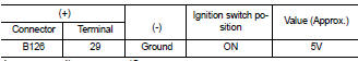
3.CHECK POWER SUPPLY CIRCUIT (BLUETOOTH CONTROL UNIT SIDE)
1. Connect Bluetooth control unit connector.
2. Turn ignition switch ON.
3. Check voltage between Bluetooth control unit harness connector
and ground.
Is proper voltage present?
YES >> Inspection End.
NO >> Replace Bluetooth control unit. Refer to AV-235,
"Removal and Installation - Sedan".
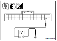
4.CHECK GROUND CIRCUIT
1. Turn ignition switch OFF.
2. Disconnect Bluetooth control unit and microphone connectors.
3. Check continuity between microphone harness connector R7
terminal 2 and Bluetooth control unit harness connector B126
terminal 8.
Is continuity present?
YES >> Inspection End.
NO >> Repair harness or connector.
Diagnosis Procedure
1.CHECK FUSE
Check that the following fuses of the Bluetooth control unit are not blown.
Are the fuses OK?
YES >> GO TO 2
NO >> Be sure to eliminate cause ...
Description
The audio unit sends audio signals to the BOSE speaker amp. The BOSE speaker
amp. amplifies the audio
signals before sending them to the door speakers using the audio signal
circuit ...
Other materials: Booster seats
For additional information on installing a
booster seat in your vehicle, follow the instructions
outlined in this section.
Precautions on booster seats
WARNING
If a booster seat and seat belt are not
used properly, the risk of a child being
injured or killed in a sudden stop or collision
greatly inc ...
Heated seat switches (if so equipped)
WARNING
Do not use or allow occupants to use
the seat heater if you or the occupants
cannot monitor elevated seat temperatures
or have an inability to feel
pain in body parts that contact the
seat. Use of the seat heater by such
people could result in serious injury.
CAUTION
The battery could run ...
Front power seat adjustment
(if so equipped)
Operating tips
The power seat motor has an auto-reset
overload protection circuit. If the motor
stops during operation, wait 30 seconds
then reactivate the switch.
Do not operate the power seat switch for
a long period of time when the engine is
off. This will discharge the battery.
For add ...

 Bluetooth control unit
 Door speaker (coupe)