Nissan Altima (L32) 2007-2012 Service Manual: Microphone signal circuit (sedan)
Description
Voice signals are transmitted from the microphone to the Bluetooth control unit using the microphone signal circuits.
Diagnosis Procedure
1.CHECK HARNESS BETWEEN BLUETOOTH CONTROL UNIT AND MICROPHONE
1. Turn ignition switch OFF.
2. Disconnect Bluetooth control unit connector and microphone connector.
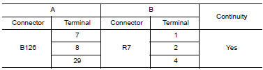
3. Check continuity between Bluetooth control unit harness connector B126 (A) and microphone harness connector R7 (B).
4. Check continuity between Bluetooth control unit harness connector B126 (A) and ground.
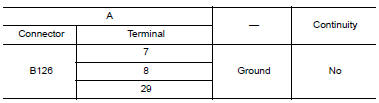
Are the continuity test results as specified? YES >> GO TO 2
NO >> Repair harness or connector.
2.CHECK MICROPHONE POWER SUPPLY
1. Connect Bluetooth control unit connector and microphone connector.
2. Turn ignition switch ON.
3. Check voltage between microphone harness connector R7 terminal 4 and ground.

Is voltage reading approx. 5 volts? YES >> GO TO 3
NO >> Replace Bluetooth control unit. Refer to AV-235, "Removal and Installation - Sedan".
3.CHECK MICROPHONE SIGNAL
Check signal between Bluetooth control unit harness connector B126 terminals 7 and 8.

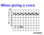
Are voltage readings as specified? YES >> Replace Bluetooth control unit. Refer to AV-235, "Removal and Installation - Sedan".
NO >> Replace microphone. Refer to AV-233, "Removal and Installation".
 Microphone signal circuit (coupe)
 ECU diagnosis