Nissan Altima (L32) 2007-2012 Service Manual: B2615 blower relay circuit
Description
BCM controls the various electrical components and simultaneously supplies power according to the power supply position.
BCM checks the power supply position internally.
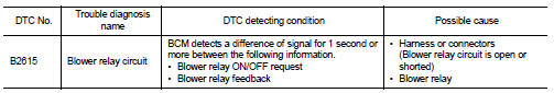
DTC Logic
DTC DETECTION LOGIC
DTC CONFIRMATION PROCEDURE
1. PERFORM DTC CONFIRMATION PROCEDURE
1. Turn ignition switch ON under the following conditions, and wait for at least 1 second.
- CVT selector lever is in the P or N position.
- Release brake pedal.
2. Check “Self diagnostic result” with CONSULT-III.
Is DTC detected? YES >> Go to PCS-68, "Diagnosis Procedure".
NO >> Inspection End.
Diagnosis Procedure
1. CHECK BLOWER RELAY POWER SUPPLY
1. Turn ignition switch OFF.
2. Disconnect blower relay.
3. Check voltage between blower relay harness connector and ground under the following conditions.
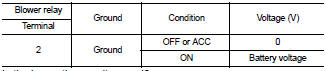
Is the inspection result normal? YES >> GO TO 3
NO >> GO TO 2
2. CHECK BLOWER RELAY POWER SUPPLY CIRCUIT
1. Turn ignition switch OFF.
2. Disconnect BCM harness connector.
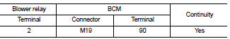
3. Check continuity between blower relay harness connector (A) and BCM harness connector (B).
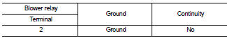
4. Check continuity between blower relay harness connector (A) and ground.
Is the inspection result normal? YES >> GO TO 6
NO >> Repair or replace harness.
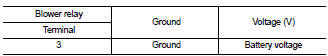
3. CHECK BLOWER RELAY GROUND CIRCUIT
1. Turn ignition switch OFF.
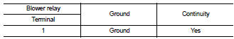
2. Check continuity between blower relay harness connector and ground.
Is the inspection result normal? YES >> GO TO 4
NO >> Repair blower relay ground circuit.
4.CHECK BLOWER RELAY POWER SUPPLY CIRCUIT-2
Check voltage between blower relay harness connector and ground.
Is the inspection result normal? YES >> GO TO 5
NO >> Repair or replace harness.
5. CHECK BLOWER RELAY
Refer to PCS-70, "Component Inspection (Blower Relay)".
Is the inspection result normal? YES >> GO TO 6
NO >> Replace blower relay.
6. CHECK INTERMITTENT INCIDENT
Refer to GI-42, "Intermittent Incident".
>> Inspection End.
Component Inspection (Blower Relay)
1. CHECK BLOWER RELAY
1. Turn ignition switch OFF.
2. Remove blower relay.
3. Check the continuity between blower relay terminals under the following conditions.
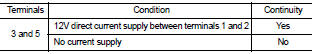
Is the inspection result normal? YES >> Inspection End.
NO >> Replace blower relay.
 B2614 ACC relay circuit
 B2616 ignition relay circuit