Nissan Altima (L32) 2007-2012 Service Manual: On-vehicle maintenance
ENGINE COOLANT
System Inspection
WARNING: • Never remove the radiator cap when the engine is hot. Serious burns could occur from high pressure coolant escaping from the radiator.
• Wrap a thick cloth around the cap. Slowly push down and turn it a quarter turn to allow built-up pressure to escape. Carefully remove the cap by pushing down and turning it all the way.
CHECKING COOLING SYSTEM HOSES
Check hoses for the following: • Improper attachment
• Leaks
• Cracks
• Damage
• Loose connections
• Chafing
• Deterioration
CHECKING RESERVOIR LEVEL
• Check if the reservoir tank coolant level is within MIN to MAX range when the engine is cool.
• Adjust coolant level if it is too much or too little.
CHECKING COOLING SYSTEM FOR LEAKS
To check for leaks, apply pressure to the cooling system using suitable tool (A) and Tool (B).
Tool number : EG17650301 (J-33984-A)
Testing pressure : 157 kPa (1.6 kg/cm2, 23 psi)
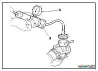
WARNING: Never remove the radiator cap when the engine is hot. Serious burns could occur from high pressure coolant escaping from the radiator.
CAUTION: Higher pressure than specified may cause radiator damage.
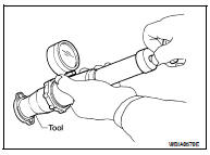
CHECKING RADIATOR CAP
1. Inspect the radiator cap.
• Replace the cap if the metal plunger cannot be seen around the edge of the black rubber gasket.
• Replace the cap if deposits of waxy residue or other foreign material are on the black rubber gasket or the metal retainer.
NOTE: Thoroughly wipe out the radiator filler neck to remove any waxy residue or foreign material.
2. Pull the negative-pressure valve to open it and check that it closes completely when released.
• Check that there is no dirt or damage on the valve seat of the radiator cap negative-pressure valve.
• Check that there are no abnormalities in the opening and closing conditions of the negative-pressure valve.
3. Check radiator cap relief pressure using suitable tool and Tool.
Tool number : EG17650301 (J-33984-A)
Standard: 122.3 – 151.7 kPa (1.2 – 1.5 kg/cm2, 18 – 22 psi)
Limit: 107 kPa (1.1 kg/cm2, 16 psi)
• When connecting the radiator cap to the tester, apply water or coolant to the cap seal surface.
• Replace the radiator cap if there is an abnormality in the negative- pressure valve, or if the open-valve pressure is outside of the standard values.
CHECKING RADIATOR
Check radiator for sludge or clogging. If necessary, clean radiator as follows: • Be careful not to bend or damage the radiator fins.
• When radiator is cleaned without removing, remove all surrounding parts such as cooling fan shroud and horns. Then tape the harness and electrical connectors to prevent water from entering.
1. Apply water by hose to the back side of the radiator core, with the hose pointed vertically downward.
2. Apply water again to all radiator core surfaces once per minute.
3. Stop washing if any dirt no longer rinse out from the radiator.
4. Blow air into the back side of radiator core, with the air hose pointed vertically downward.
• Use compressed air lower than 490 kPa (5 kg/cm2, 71 psi) and keep distance more than 30 cm (11.8 in).
5. Blow air again into all the radiator core surfaces once per minute until no water sprays out.
6. Check for leaks.
Changing Engine Coolant
WARNING: • To avoid being scalded, never change the coolant when the engine is hot.
• Wrap a thick cloth around cap and carefully remove the cap. First, turn the cap a quarter of a turn to release built-up pressure. Then push down and turn the cap all the way to remove.
DRAINING ENGINE COOLANT
1. Remove the engine undercover using power tool.
2. Open the radiator drain plug at the bottom of the radiator and remove the radiator filler cap. This is the only step required when partially draining the cooling system (radiator only).
CAUTION: Do not allow the coolant to contact the drive belts.
3. Follow this step for heater core removal/replacement only. Disconnect the upper heater hose at the engine side and apply moderate air pressure [103.46 kPa (15 psi, 1.055 kg/cm2) maximum air pressure] into the hose for 30 seconds to blow the excess coolant out of the heater core.
4. When draining all of the coolant in the system, remove the reservoir tank and drain the coolant, then clean the reservoir tank before installation.
CAUTION:
Do not allow the coolant to contact the drive belts.
5. When draining all of the coolant in the system for engine removal or repair, open the drain plug on the cylinder block.
6. Check the drained coolant for contaminants such as rust, corrosion or discoloration.
If the coolant is contaminated, flush the engine cooling system.
REFILLING ENGINE COOLANT
1. Install the radiator drain plug. If the cooling system was drained completely, install the reservoir tank and the cylinder block drain plugs.
• The radiator must be completely empty of coolant and water.
• Apply sealant to the threads of the cylinder block drain plugs. Use Genuine High Performance Thread Sealant or equivalent. Refer to GI-15, "Recommended Chemical Products and Sealants".
Radiator drain plug : Refer to CO-38, "Removal and Installation".
Cylinder block front drain plug : Refer to EM-76, "Disassembly and Assembly".
Cylinder block RH drain plug : Refer to EM-76, "Disassembly and Assembly".
2. If disconnected, reattach the upper radiator hose at the engine side.
3. Set the vehicle heater controls to the full HOT and heater ON position. Turn the vehicle ignition ON with the engine OFF as necessary to activate the heater mode.
4. Install the Tool by installing the radiator cap adapter onto the radiator neck opening. Then attach the gauge body assembly with the refill tube and the venturi assembly to the radiator cap adapter.
Tool number : KV991J0070 (J-45695)
5. Insert the refill hose into the coolant mixture container that is placed at floor level. Make sure the ball valve is in the closed position.
• Use Genuine NISSAN Engine Coolant or equivalent, mixed 50/50 with distilled water or demineralized water.
Refer to MA-12, "Engine Oil Recommendation".
6. Install an air hose to the venturi assembly, the air pressure must be within specification.

CAUTION: The compressed air supply must be equipped with an air dryer.
7. The vacuum gauge will begin to rise and there will be an audible hissing noise. During this process open the ball valve on the refill hose slightly. Coolant will be visible rising in the refill hose. Once the refill hose is full of coolant, close the ball valve. This will purge any air trapped in the refill hose.
8. Continue to draw the vacuum until the gauge reaches 28 inches of vacuum. The gauge may not reach 28 inches in high altitude locations, use the vacuum specifications based on the altitude above sea level.
9. When the vacuum gauge has reached the specified amount, disconnect the air hose and wait 20 seconds to see if the system loses any vacuum. If the vacuum level drops, perform any necessary repairs to the system and repeat steps 6 - 8 to bring the vacuum to the specified amount. Recheck for any leaks.
10. Place the coolant container (with the refill hose inserted) at the same level as the top of the radiator. Then open the ball valve on the refill hose so the coolant will be drawn up to fill the cooling system. The cooling system is full when the vacuum gauge reads zero.
CAUTION: Do not allow the coolant container to get too low when filling, to avoid air from being drawn into the cooling system.
11. Remove the Tool from the radiator neck opening.
12. Fill the cooling system reservoir tank to the specified level and install the radiator cap. Run the engine to warm up the cooling system and top up the system as necessary.
FLUSHING COOLING SYSTEM
1. Fill the radiator from the filler neck above the radiator upper hose and reservoir tank with clean water and reinstall radiator filler cap.
2. Run the engine until it reaches normal operating temperature.
3. Rev the engine two or three times under no-load.
4. Stop the engine and wait until it cools down.
5. Drain the water from the system. Refer to CO-35, "Changing Engine Coolant".
6. Repeat steps 1 through 5 until clear water begins to drain from the radiator.
 Overheating cause analysis
 On-vehicle repair