Nissan Altima (L32) 2007-2012 Service Manual: Front power window switch
Description
Main power window and door lock/unlock switch, power window and door lock/unlock switch RH and BCM transmit and receive the signal by power window serial link.
The signal mentioned below is transmitted from BCM to main power window and door lock/unlock switch and power window and door lock/unlock switch RH
• Keyless power window down signal
The signal mentioned below is transmitted from main power window and door lock/unlock switch to power window and door lock/unlock switch RH
• Front door window RH operation signal
• Power window control by key cylinder switch signal
• Retained power operation signal
• Power window lock switch signal
Component Function Check
1. CHECK POWER WINDOW AND DOOR LOCK/UNLOCK SWITCH RH OUTPUT SIGNAL
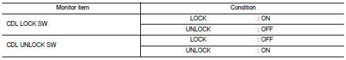
Check (“CDL LOCK SW ”, “CDL UNLOCK SW”) in “DATA MONITOR” mode for “POWER DOOR LOCK SYSTEM” with CONSULT-III. Refer to BCS-19, "DOOR LOCK : CONSULT-III Function (BCM - DOOR LOCK)".
Is the inspection result normal? YES >> Power window serial link is OK.
NO >> Refer to PWC-333, "FRONT POWER WINDOW SWITCH : Diagnosis Procedure".
Diagnosis Procedure
Power Window Serial Link Check
1. CHECK POWER WINDOW AND DOOR LOCK/UNLOCK SWITCH RH
1. Remove Intelligent Key, and close the front door LH and RH.
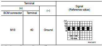
2. Check signal between BCM connector and ground with oscilloscope when door lock and unlock switch (LH and RH) is turned to “LOCK” or “UNLOCK”.
3. Check that signals which are shown in the figure below can be detected during 10 second just after door lock and unlock switch (LH and RH) is turned to “LOCK” or “UNLOCK”.
Is the inspection result normal? YES >> Power window serial link is OK.
NO >> GO TO 2
2. CHECK POWER WINDOW SERIAL LINK CIRCUIT
1. Turn ignition switch OFF.
2. Disconnect BCM.
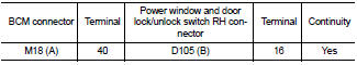
3. Check continuity between BCM connector (A) and power window and door lock/unlock switch RH connector (B).
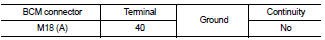
4. Check continuity between BCM connector (A) and ground.
Is the inspection result normal? YES >> Replace main power window and door lock/unlock switch. Refer to PWC-411, "Removal and Installation". After that, refer to PWC-307, "POWER WINDOW MAIN SWITCH : Special Repair Requirement".
NO >> Repair or replace harness.
 Power window main switch
 Power window lock switch