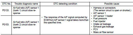
Nissan Altima (L32) 2007-2012 Service Manual: P0133, P0153 A/F sensor 1
Description
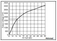
The air fuel ratio (A/F) sensor 1 is a planar one-cell limit current sensor.
The sensor element of the A/F sensor 1 is composed an electrode layer, which transports ions. It has a heater in the element.
The sensor is capable of precise measurement = 1, but also in the lean and rich range. Together with its control electronics, the sensor outputs a clear, continuous signal throughout a wide range.
The exhaust gas components diffuse via the diffusion layer at the sensor cell. An electrode layer is applied voltage, and this current relative oxygen density in lean. Also this current relative hydrocarbon density in rich.
Therefore, the A/F sensor 1 is able to indicate air fuel ratio by this electrode layer of current. In addition, a heater is integrated in the sensor to ensure the required operating temperature of approximately 800°C (1,472°F).
DTC Logic
DTC DETECTION LOGIC
To judge the malfunction of A/F sensor 1, this diagnosis measures response time of the A/F signal computed by ECM from the A/F sensor 1 signal. The time is compensated by engine operating (speed and load), fuel feedback control constant, and the A/F sensor 1 temperature index. Judgment is based on whether the compensated time (the A/F signal cycling time index) is inordinately long or not.
DTC CONFIRMATION PROCEDURE
1.PRECONDITIONING
If DTC Confirmation Procedure has been previously conducted, always perform the following before conducting the next test.
1. Turn ignition switch OFF and wait at least 10 seconds.
2. Turn ignition switch ON.
3. Turn ignition switch OFF and wait at least 10 seconds.
TESTING CONDITION: Before performing the following procedure, confirm that battery voltage is more than 11 V at idle.
Will CONSULT-III be used? YES >> GO TO 2.
NO >> GO TO 5.
2.PERFORM DTC CONFIRMATION PROCEDURE-I

1. Start engine and warm it up to normal operating temperature.
2. Turn ignition switch OFF and wait at least 10 seconds.
3. Turn ignition switch ON.
4. Turn ignition switch OFF and wait at least 10 seconds.
5. Start engine and keep the engine speed between 3,500 and 4,000 rpm for at least 1 minute under no load.
6. Let engine idle for 1 minute.
7. Select “A/F SEN1(B1) P1278/P1279” (for DTC P0133) or “A/F SEN1(B2) P1288/P1289” (for DTC P0153) of “A/F SEN1” in “DTC WORK SUPPORT” mode with CONSULT-III.
8. Touch “START”.
Is COMPLETED displayed? YES >> GO TO 3.
NO >> GO TO 4.
3.PERFORM DTC CONFIRMATION PROCEDURE-II
Check that “OK” is displayed after touching “SELF-DIAG RESULT”.
Is OK displayed? YES >> INSPECTION END
NO >> Go to EC-1239, "Diagnosis Procedure".
4.PERFORM DTC CONFIRMATION PROCEDURE-III
1. After perform the following procedure, “TESTING” will be displayed on the CONSULT-III screen.
- Increase the engine speed up to between 4,000 and 5,000 rpm and maintain that speed for 10 seconds.
- Fully release accelerator pedal and then let engine idle for approximately 10 seconds.
If “TESTING” is not displayed after 10 seconds, go to EC-1167, "Component Function Check".
2. Wait for approximately 20 seconds at idle under the condition that “TESTING” is displayed on the CONSULT- III screen.
3. Check that “TESTING” changes to “COMPLETED”.
If “TESTING” changed to “OUT OF CONDITION”, go to EC-1167, "Component Function Check".
4. Check that “OK” is displayed after touching “SELF-DIAG RESULT”.
Is OK displayed? YES >> INSPECTION END
NO >> Go to EC-1239, "Diagnosis Procedure".
5.CHECK MIXTURE RATIO SELF-LEARNING VALUE

1. Start engine and warm it up to normal operating temperature.
2. Select Service $01 with GST.
3. Calculate the total value of “Short term fuel trim” and “Long term fuel trim” indications.
Is the total percentage within ±15%? YES >> GO TO 7.
NO >> GO TO 6.
6.DETECT MALFUNCTIONING PART
Check the following.
• Intake air leakage
• Exhaust gas leakage
• Incorrect fuel pressure
• Lack of fuel
• Fuel injector
• Incorrect PCV hose connection
• PCV valve
• Mass air flow sensor
>> Repair or replace malfunctioning part.
7.PERFORM DTC CONFIRMATION PROCEDURE-IV
1. Turn ignition switch OFF and wait at least 10 seconds.
2. Turn ignition switch ON.
3. Turn ignition switch OFF and wait at least 10 seconds.
4. Start engine and keep the engine speed between 3,500 and 4,000 rpm for at least 1 minute under no load.
5. Let engine idle for 1 minute.
6. Increase the engine speed up to between 4,000 and 5,000 rpm and maintain that speed for 10 seconds.
7. Fully release accelerator pedal and then let engine idle for approximately 1 minute.
8. Check 1st trip DTC.
Is 1st trip DTC detected? YES >> Go to EC-1239, "Diagnosis Procedure".
NO >> INSPECTION END
Diagnosis Procedure
1.CHECK GROUND CONNECTION
1. Turn ignition switch OFF.
2. Check ground connection E9. Refer to Ground Inspection in GI-45, "Circuit Inspection".
Is the inspection result normal? YES >> GO TO 2.
NO >> Repair or replace ground connection.
2.RETIGHTEN A/F SENSOR 1
Loosen and retighten the A/F sensor 1. Refer to EM-136, "Removal and Installation".
>> GO TO 3.
3.CHECK EXHAUST GAS LEAKAGE
1. Start engine and run it at idle.
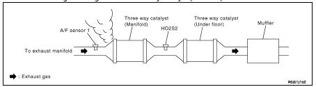
2. Listen for an exhaust gas leakage before three way catalyst (manifold).
Is exhaust gas leakage detected? YES >> Repair or replace malfunctioning part.
NO >> GO TO 4.
4.CHECK FOR INTAKE AIR LEAKAGE
Listen for an intake air leakage after the mass air flow sensor.
Is intake air leakage detected? YES >> Repair or replace malfunctioning part.
NO >> GO TO 5.
5.CLEAR MIXTURE RATIO SELF-LEARNING VALUE
1. Clear the mixture ratio self-learning value. Refer to EC-1055, "MIXTURE RATIO SELF-LEARNING VALUE CLEAR : Special Repair Requirement".
2. Run engine for at least 10 minutes at idle speed.
3. Check 1st trip DTC.
Is the 1st trip DTC P0171, P0172, P0174 or P0175 detected? Is it difficult to start engine?
YES >> Perform trouble diagnosis for DTC P0171, P0174 or P0172, P0175. Refer to EC-1266, "DTC Logic" or EC-1270, "DTC Logic".
NO >> GO TO 6.
6.CHECK AIR FUEL RATIO (A/F) SENSOR 1 POWER SUPPLY CIRCUIT
1. Turn ignition switch OFF.
2. Disconnect A/F sensor 1 harness connector.
3. Turn ignition switch ON.
4. Check the voltage between A/F sensor 1 harness connector and ground.
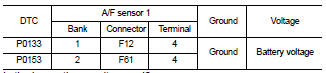
Is the inspection result normal? YES >> GO TO 8.
NO >> GO TO 7.
7.DETECT MALFUNCTIONING PART
Check the following.
• IPDM E/R harness connector F10
• 15 A fuse (No. 37) • Harness for open or short between A/F sensor 1 and IPDM E/R
>> Repair or replace harness or connectors.
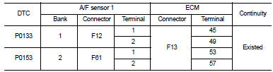
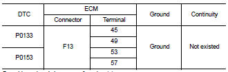
8.CHECK A/F SENSOR 1 INPUT SIGNAL CIRCUIT FOR OPEN AND SHORT
1. Turn ignition switch OFF.
2. Disconnect ECM harness connector.
3. Check the continuity between A/F sensor 1 harness connector and ECM harness connector.
4. Check the continuity between A/F sensor 1 harness connector and ground, or ECM harness connector ground.
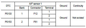
5. Also check harness for short to power.
Is the inspection result normal? YES >> GO TO 9.
NO >> Repair open circuit, short to ground or short to power in harness or connectors.
9.CHECK AIR FUEL RATIO (A/F) SENSOR 1 HEATER
Refer to EC-1186, "Component Inspection".
Is the inspection result normal? YES >> GO TO 10.
NO >> GO TO 13.
10.CHECK MASS AIR FLOW SENSOR
Refer to EC-1197, "Component Inspection".
Is the inspection result normal? YES >> GO TO 11.
NO >> Replace mass air flow sensor.
11.CHECK PCV VALVE
Refer to EC-1502, "Component Inspection".
Is the inspection result normal? YES >> GO TO 12.
NO >> Repair or replace PCV valve.
12.CHECK INTERMITTENT INCIDENT
Perform GI-42, "Intermittent Incident".
Is the inspection result normal? YES >> GO TO 13.
NO >> Repair or replace malfunctioning part.
13.REPLACE AIR FUEL RATIO (A/F) SENSOR 1
Replace malfunctioning air fuel ratio (A/F) sensor 1. CAUTION: • Discard any A/F sensor which has been dropped from a height of more than 0.5 m (19.7 in) onto a hard surface such as a concrete floor; use a new one.
• Before installing new A/F sensor, clean exhaust system threads using Oxygen Sensor Thread Cleaner [commercial service tool (J-43897-18 or J-43897-12)] and approved anti-seize lubricant (commercial service tool).
>> INSPECTION END
 P0132, P0152 A/F sensor 1
 P0137, P0157 HO2S2