Nissan Altima (L32) 2007-2012 Service Manual: P0139 HO2S2
Description
The heated oxygen sensor 2, after three way catalyst (manifold), monitors the oxygen level in the exhaust gas on each bank.
Even if switching characteristics of the air fuel ratio (A/F) sensor 1 are shifted, the air-fuel ratio is controlled to stoichiometric, by the signal from the heated oxygen sensor 2.
This sensor is made of ceramic zirconia. The zirconia generates voltage from approximately 1V in richer conditions to 0V in leaner conditions.
Under normal conditions the heated oxygen sensor 2 is not used for engine control operation.
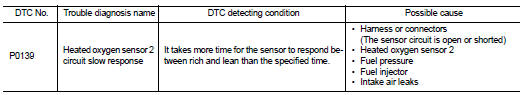
DTC Logic
DTC DETECTION LOGIC
The heated oxygen sensor 2 has a much longer switching time between rich and lean than the air fuel ratio (A/F) sensor 1. The oxygen storage capacity of the three way catalyst (mamifold) causes the longer switching time. To judge the malfunctions of heated oxygen sensor 2, ECM monitors whether the switching response of the sensor's voltage is faster than specified during the various driving condition such as fuel-cut.
DTC CONFIRMATION PROCEDURE
1.INSPECTION START
Do you have CONSULT-III? Do you have CONSULT-III? YES >> GO TO 2.
NO >> GO TO 5.
2.PRECONDITIONING
If DTC Confirmation Procedure has been previously conducted, always turn ignition switch OFF and wait at least 10 seconds before conducting the next test.
>> GO TO 3.
3.PERFORM DTC CONFIRMATION PROCEDURE

1. Turn ignition switch ON and select “DATA MONITOR” mode with CONSULT-III.
2. Start engine and warm it up to the normal operating temperature.
3. Start engine and warm it up to the normal operating temperature.
4. Start engine and keep the engine speed between 3,500 and 4,000 rpm for at least 1 minute under no load.
5. Let engine idle for 1 minute.
6. Open engine hood.
7. Select “HO2S2 (B1) P0139” of “HO2S2” in “DTC WORK SUPPORT” mode with CONSULT-III.
8. Follow the instruction of CONSULT-III.
NOTE: It will take at most 10 minutes until “COMPLETED” is displayed.
9. Touch “SELF-DIAG RESULT”.
Which is displayed on CONSULT-III? OK >> INSPECTION END
NG >> GO TO 4.
CAN NOT BE DIAGNOSED>>GO TO 4.
4.PERFORM THE RESULT OF DTC CONFIRMATION PROCEDURE
1. Turn ignition switch OFF and leave the vehicle in a cool place (soak the vehicle).
2. Perform DTC CONFIRMATION PROCEDURE again.
>> GO TO 3.
5.PERFORM COMPONENT FUNCTION CHECK
Perform component function check. Refer to EC-754, "Component Function Check".
NOTE: Use component function check to check the overall function of the heated oxygen sensor 2 circuit. During this check, a 1st trip DTC might not be confirmed.
Is the inspection result normal? YES >> INSPECTION END
NO >> Go to EC-755, "Diagnosis Procedure".
Component Function Check
1.PERFORM COMPONENT FUNCTION CHECK-I

1. Start engine and warm it up to the normal operating temperature.
2. Turn ignition switch OFF and wait at least 10 seconds.
3. Start engine and keep the engine speed between 3,500 and 4,000 rpm for at least 1 minute under no load.
4. Let engine idle for 1 minute.
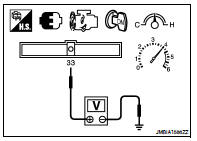
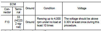
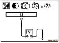
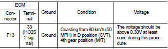
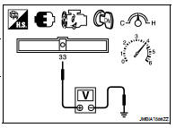
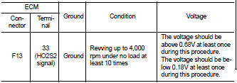
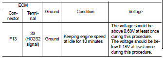
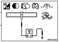
5. Check the voltage between ECM harness connector and ground under the following condition.
Is the inspection result normal? YES >> INSPECTION END
NO >> GO TO 2.
2.PERFORM COMPONENT FUNCTION CHECK-II
Check the voltage between ECM harness connector and ground under the following condition.
Is the inspection result normal? YES >> INSPECTION END
NO >> GO TO 3.
3.PERFORM COMPONENT FUNCTION CHECK-III
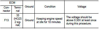
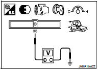
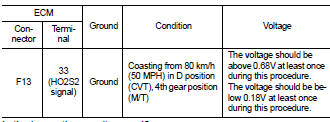
Check the voltage between ECM harness connector and ground under the following condition.
Is the inspection result normal? YES >> INSPECTION END
NO >> Go to EC-755, "Diagnosis Procedure".
Diagnosis Procedure
1.CHECK GROUND CONNECTION
1. Turn ignition switch OFF.
2. Check ground connection E9. Refer to Ground Inspection in GI-45, "Circuit Inspection".
Is the inspection result normal? YES >> GO TO 2.
NO >> Repair or replace ground connection.
2.CLEAR THE MIXTURE RATIO SELF-LEARNING VALUE
1. Clear the mixture ratio self-learning value. Refer to EC-568, "MIXTURE RATIO SELF-LEARNING VALUE CLEAR : Special Repair Requirement".
2. Run engine for at least 10 minutes at idle speed.
Is the 1st trip DTC P0171 or P0172 detected? Is it difficult to start engine? YES >> Perform trouble diagnosis for DTC P0171 or P0172. Refer to EC-759, "DTC Logic" or EC-763, "DTC Logic".
NO >> GO TO 3.
3.CHECK HO2S2 GROUND CIRCUIT FOR OPEN AND SHORT
1. Turn ignition switch OFF.
2. Disconnect heated oxygen sensor 2 harness connector.
3. Disconnect ECM harness connector.
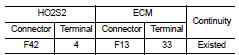
4. Check the continuity between HO2S2 harness connector and ECM harness connector.
5. Also check harness for short to ground and short to power.
Is the inspection result normal? YES >> GO TO 4.
NO >> Repair open circuit or short to ground or short to power in harness or connectors.
4.CHECK HO2S2 INPUT SIGNAL CIRCUIT FOR OPEN AND SHORT
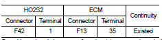
1. Check the continuity between HO2S2 harness connector and ECM harness connector.
2. Check the continuity between HO2S2 harness connector or ECM harness connector and ground.
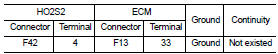
3. Also check harness for short to power.
Is the inspection result normal? YES >> GO TO 5.
NO >> Repair open circuit or short to ground or short to power in harness or connectors.
5.CHECK HEATED OXYGEN SENSOR 2
Refer to EC-756, "Component Inspection".
Is the inspection result normal? YES >> GO TO 7.
NO >> GO TO 6.
6.REPLACE HEATED OXYGEN SENSOR 2
Replace heated oxygen sensor 2.
CAUTION: • Discard any sensor which has been dropped from a height of more than 0.5 m (19.7 in) onto a hard surface such as a concrete floor; use a new one.
• Before installing new sensor, clean exhaust system threads using oxygen sensor thread cleaner tool [commercial service tool: (J-43897-18) or J43897-12] and approved anti-seize lubricant (commercial service tool). >> INSPECTION END
7.CHECK INTERMITTENT INCIDENT
Refer to GI-42, "Intermittent Incident".
>> INSPECTION END
Component Inspection
1.INSPECTION START
Do you have CONSULT-III? Do you have CONSULT-III? YES >> GO TO 2.
NO >> GO TO 3.
2.CHECK HEATED OXYGEN SENSOR 2

1. Turn ignition switch ON and select “DATA MONITOR” mode with CONSULT-III.
2. Start engine and warm it up to the normal operating temperature.
3. Turn ignition switch OFF and wait at least 10 seconds.
4. Start engine and keep the engine speed between 3,500 and 4,000 rpm for at least 1 minute under no load.
5. Let engine idle for 1 minute.
6. Select “FUEL INJECTION” in “ACTIVE TEST” mode, and select “HO2S2 (B1)” as the monitor item with CONSULT-III.
7. Check “HO2S2 (B1)” at idle speed when adjusting “FUEL INJECTION” to ±25%.
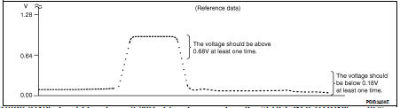
“HO2S2 (B1)” should be above 0.68V at least once when the “FUEL INJECTION” is +25%.
“HO2S2 (B1)” should be below 0.18V at least once when the “FUEL INJECTION” is −25%.
Is the inspection result normal? YES >> INSPECTION END
NO >> GO TO 6.
3.CHECK HEATED OXYGEN SENSOR 2-I

1. Start engine and warm it up to the normal operating temperature.
2. Turn ignition switch OFF and wait at least 10 seconds.
3. Start engine and keep the engine speed between 3,500 and 4,000 rpm for at least 1 minute under no load.
4. Let engine idle for 1 minute.
5. Check the voltage between ECM harness connector and ground under the following condition.
Is the inspection result normal? YES >> INSPECTION END
NO >> GO TO 4.
4.CHECK HEATED OXYGEN SENSOR 2-II
Check the voltage between ECM harness connector and ground under the following condition.
Is the inspection result normal? YES >> INSPECTION END
NO >> GO TO 5.
5.CHECK HEATED OXYGEN SENSOR 2-III
Check the voltage between ECM harness connector and ground under the following condition.
Is the inspection result normal? YES >> INSPECTION END
NO >> GO TO 6.
6.REPLACE HEATED OXYGEN SENSOR 2
Replace heated oxygen sensor 2.
CAUTION: • Discard any sensor which has been dropped from a height of more than 0.5 m (19.7 in) onto a hard surface such as a concrete floor; use a new one.
• Before installing new sensor, clean exhaust system threads using oxygen sensor thread cleaner tool [commercial service tool: (J-43897-18) or J43897-12] and approved anti-seize lubricant (commercial service tool). >> INSPECTION END
 P0138 HO2S2
 P0171 fuel injection system function