Nissan Altima (L32) 2007-2012 Service Manual: P0181 FTT sensor
Description
The fuel tank temperature sensor is used to detect the fuel temperature inside the fuel tank. The sensor modifies a voltage signal from the ECM. The modified signal returns to the ECM as the fuel temperature input. The sensor uses a thermistor which is sensitive to the change in temperature. The electrical resistance of the thermistor decreases as temperature increases.
<Reference data>
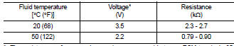
*: These data are reference values and are measured between ECM terminals 95 (Fuel tank temperature sensor) and 104 (Sensor ground).
DTC Logic
DTC DETECTION LOGIC
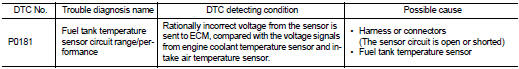
DTC CONFIRMATION PROCEDURE
1.PRECONDITIONING
If DTC Confirmation Procedure has been previously conducted, always perform the following before conducting the next test.
1. Turn ignition switch OFF and wait at least 10 seconds.
2. Turn ignition switch ON.
3. Turn ignition switch OFF and wait at least 10 seconds.
>> GO TO 2.
2.PERFORM DTC CONFIRMATION PROCEDURE-I
1. Turn ignition switch ON and wait at least 10 seconds.
2. Check 1st trip DTC.
Is 1st trip DTC detected? YES >> Go to EC-1275, "Diagnosis Procedure".
NO >> GO TO 3.
3.CHECK ENGINE COOLANT TEMPERATURE

1. Select “COOLAN TEMP/S” in “DATA MONITOR” with CONSULT-III.
2. Check “COOLAN TEMP/S” value.

Follow the procedure “With CONSULT-III” above.
Is “COOLAN TEMP/S” less than 60°C (140°F)? YES >> INSPECTION END
NO >> GO TO 4.
4.PERFORM DTC CONFIRMATION PROCEDURE-II

1. Cool engine down until “COOLAN TEMP/S” is less than 60°C (140°F).
2. Wait at least 10 seconds.
3. Check 1st trip DTC.

Follow the procedure “With CONSULT-III” above.
Is 1st trip DTC detected? YES >> Go to EC-1275, "Diagnosis Procedure".
NO >> INSPECTION END
Diagnosis Procedure
1.CHECK GROUND CONNECTION
1. Turn ignition switch OFF.
2. Check ground connection E9. Refer to Ground Inspection in GI-45, "Circuit Inspection".
Is the inspection result normal? YES >> GO TO 2.
NO >> Repair or replace ground connection.
2.CHECK FUEL TANK TEMPERATURE SENSOR POWER SUPPLY CIRCUIT
1. Turn ignition switch OFF.
2. Disconnect “fuel level sensor unit and fuel pump” harness connector.
3. Turn ignition switch ON.
4. Check the voltage between “fuel level sensor unit and fuel pump” harness connector and ground.
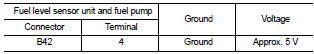
Is the inspection result normal? YES >> GO TO 4.
NO >> GO TO 3.
3.DETECT MALFUNCTIONING PART
Check the following.
• Harness connectors B10, E29
• Harness for open or short between ECM and “fuel level sensor unit and fuel pump” >> Repair open circuit, short to ground or short to power in harness or connector.
4.CHECK FUEL TANK TEMPERATURE SENSOR GROUND CIRCUIT FOR OPEN AND SHORT
1. Turn ignition switch OFF.
2. Disconnect ECM harness connector.
3. Check the continuity between “fuel level sensor unit and fuel pump” harness connector and ECM harness connector.
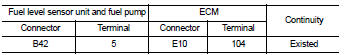
4. Also check harness for short to ground and short to power.
Is the inspection result normal? YES >> GO TO 6.
NO >> GO TO 5.
5.DETECT MALFUNCTIONING PART
Check the following.
• Harness connectors B1, M6
• Harness connectors E30, M1
• Harness for open or short between “fuel level sensor unit and fuel pump” and ECM
>> Repair open circuit, short to ground or short to power in harness or connector.
6.CHECK FUEL TANK TEMPERATURE SENSOR
Refer to EC-1276, "Component Inspection".
Is the inspection result normal? YES >> GO TO 7.
NO >> Replace “fuel level sensor unit and fuel pump”.
7.CHECK INTERMITTENT INCIDENT
Refer to GI-42, "Intermittent Incident".
>> INSPECTION END
Component Inspection
1.CHECK FUEL TANK TEMPERATURE SENSOR
1. Turn ignition switch OFF.
2. Remove fuel level sensor unit.
3. Check resistance between “fuel level sensor unit and fuel pump” terminals by heating with hot water as shown in the figure.
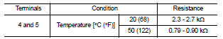
Is the inspection result normal? YES >> INSPECTION END
NO >> Replace “fuel level sensor unit and fuel pump”.
 P0172, P0175 Fuel injection system function
 P0182, P0183 FTT sensor