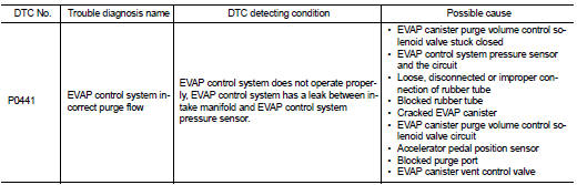
Nissan Altima (L32) 2007-2012 Service Manual: P0441 evap control system
DTC Logic
DTC DETECTION LOGIC
NOTE: If DTC P0441 is displayed with other DTC such as P2122, P2123, P2127, P2128 or P2138, first perform trouble diagnosis for other DTC.
In this evaporative emission (EVAP) control system, purge flow occurs during non-closed throttle conditions.
Purge volume is related to air intake volume. Under normal purge conditions (non-closed throttle), the EVAP canister purge volume control solenoid valve is open to admit purge flow. Purge flow exposes the EVAP control system pressure sensor to intake manifold vacuum.
Under normal conditions (non-closed throttle), sensor output voltage indicates if pressure drop and purge flow are adequate. If not, a malfunction is determined.
DTC CONFIRMATION PROCEDURE
1.INSPECTION START
Do you have CONSULT-III? Do you have CONSULT-III? YES >> GO TO 2.
NO >> GO TO 6.
2.PRECONDITIONING
If DTC Confirmation Procedure has been previously conducted, always turn ignition switch OFF and wait at least 10 seconds before conducting the next test.
TESTING CONDITION:
Always perform test at a temperature of 5°C (41°F) or more.
>> GO TO 3.
3.PERFORM DTC CONFIRMATION PROCEDURE-I

1. Start engine and warm it up to normal operating temperature.
2. Turn ignition switch OFF and wait at least 10 seconds.
3. Start engine and let it idle for at least 70 seconds.
4. Select “PURG FLOW P0441” of “EVAPORATIVE SYSTEM” in “DTC WORK SUPPORT” mode with CONSULT- III.
5. Touch “START”.
Is COMPLETED displayed on CONSULT-III screen? YES >> GO TO 5.
NO >> GO TO 4.
4.PERFORM DTC CONFIRMATION PROCEDURE-II
When the following conditions are met, “TESTING” will be displayed on the CONSULT-III screen. Maintain the conditions continuously until “TESTING” changes to “COMPLETED”. (It will take at least 35 seconds.)
CAUTION: Always drive vehicle at a safe speed.
If “TESTING” is not changed for a long time, retry from step 2.
Is “COMPLETED” displayed on CONSULT-III screen? YES >> GO TO 5.
NO >> Perform DTC CONFIRMATION PROCEDURE again. GO TO 3.
5.PERFORM DTC CONFIRMATION PROCEDURE-II
Touch “SELF-DIAG RESULT”.
Which is displayed on CONSULT-III screen? OK >> INSPECTION END NG >> Go to EC-292, "Diagnosis Procedure".
6.PERFORM COMPONENT FUNCTION CHECK
Perform component function check. Refer to EC-291, "Component Function Check".
NOTE: Use component function check to check the overall monitoring function of the EVAP control system purge flow monitoring. During this check, a 1st trip DTC might not be confirmed.
Is the inspection result normal? YES >> INSPECTION END
NO >> Go to EC-292, "Diagnosis Procedure".
Component Function Check
1.PERFORM COMPONENT FUNCTION CHECK

1. Lift up drive wheels.
2. Start engine and warm it up to normal operating temperature.
3. Turn ignition switch OFF, wait at least 10 seconds.
4. Start engine and wait at least 70 seconds.
5. Set voltmeter probes to ECM harness connector and ground.
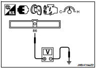
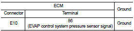
6. Check EVAP control system pressure sensor value at idle speed and note it.
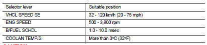
7. Establish and maintain the following conditions for at least 1 minute.
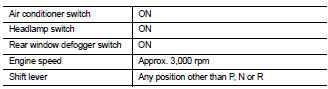
8. Verify that EVAP control system pressure sensor value stays 0.1V less than the value at idle speed (measured at step 6) for at least 1 second.
Is the inspection result normal? YES >> INSPECTION END
NO >> Go to EC-292, "Diagnosis Procedure".
Diagnosis Procedure
1.CHECK EVAP CANISTER
1. Turn ignition switch OFF.
2. Check EVAP canister for cracks.
Is the inspection result normal? YES-1 >> With CONSULT-III: GO TO 2.
YES-2 >> Without CONSULT-III: GO TO 3.
NO >> Replace EVAP canister.
2.CHECK PURGE FLOW

1. Disconnect vacuum hose connected to EVAP canister purge volume control solenoid valve at EVAP service port and install vacuum gauge. For the location of EVAP service port, refer to EC-86, "System Diagram".
2. Start engine and let it idle.
3. Select “PURG VOL CONT/V” in “ACTIVE TEST” mode with CONSULT-III.
4. Rev engine up to 2,000 rpm.
5. Touch “Qd” and “Qu” on CONSULT-III screen to adjust “PURG VOL CONT/V” opening and check vacuum existence.
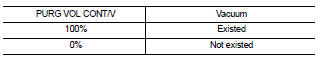
Is the inspection result normal? YES >> GO TO 7.
NO >> GO TO 4.
3.CHECK PURGE FLOW

1. Start engine and warm it up to normal operating temperature.
2. Stop engine.
3. Disconnect vacuum hose connected to EVAP canister purge volume control solenoid valve at EVAP service port and install vacuum gauge. For the location of EVAP service port, refer to EC-86, "System Diagram".
4. Start engine and let it idle.
Do not depress accelerator pedal even slightly.
5. Check vacuum gauge indication before 60 seconds passed after starting engine.
Vacuum should not exist.
6. Revving engine up to 2,000rpm after 100 seconds passed after starting engine.
Vacuum should exist.
Is the inspection result normal? YES >> GO TO 7.
NO >> GO TO 4.
4.CHECK EVAP PURGE LINE
1. Turn ignition switch OFF.
2. Check EVAP purge line for improper connection or disconnection.
Refer to EC-86, "System Diagram".
Is the inspection result normal? YES >> GO TO 5.
NO >> Repair it.
5.CHECK EVAP PURGE HOSE AND PURGE PORT
1. Disconnect purge hoses connected to EVAP service port A and EVAP canister purge volume control solenoid valve B.
2. Blow air into each hose and EVAP purge port C.
3. Check that air flows freely.
Is the inspection result normal? YES-1 >> With CONSULT-III: GO TO 6.
YES-2 >> Without CONSULT-III: GO TO 7.
NO >> Repair or clean hoses and/or purge port.
6.CHECK EVAP CANISTER PURGE VOLUME CONTROL SOLENOID VALVE

1. Start engine.
2. Perform “PURG VOL CONT/V” in “ACTIVE TEST” mode with CONSULT-III. Check that engine speed varies according to the valve opening.
Is the inspection result normal? YES >> GO TO 8.
NO >> GO TO 7.
7.CHECK EVAP CANISTER PURGE VOLUME CONTROL SOLENOID VALVE
Refer to EC-304, "Component Inspection".
Is the inspection result normal? YES >> GO TO 8.
NO >> Replace EVAP canister purge volume control solenoid valve.
8.CHECK EVAP CONTROL SYSTEM PRESSURE SENSOR CONNECTOR
1. Disconnect EVAP control system pressure sensor harness connector.
2. Check connectors for water.
Water should not exist.
Is the inspection result normal? YES >> GO TO 9.
NO >> Replace EVAP control system pressure sensor.
9.CHECK EVAP CONTROL SYSTEM PRESSURE SENSOR FUNCTION
Refer to EC-319, "DTC Logic" for DTC P0452, EC-324, "DTC Logic" for DTC P0453.
Is the inspection result normal? YES >> GO TO 10.
NO >> Replace EVAP control system pressure sensor.
10.CHECK RUBBER TUBE FOR CLOGGING
1. Disconnect rubber tube connected to EVAP canister vent control valve.
2. Check the rubber tube for clogging.
Is the inspection result normal? YES >> GO TO 11.
NO >> Clean the rubber tube using an air blower.
11.CHECK EVAP CANISTER VENT CONTROL VALVE
Refer to EC-310, "Component Inspection".
Is the inspection result normal? YES >> GO TO 12.
NO >> Replace EVAP canister vent control valve.
12.CHECK EVAP PURGE LINE
Inspect EVAP purge line (pipe and rubber tube). Check for evidence of leaks.
Refer to EC-86, "System Diagram".
Is the inspection result normal? YES >> GO TO 13.
NO >> Replace it.
13.CLEAN EVAP PURGE LINE
Clean EVAP purge line (pipe and rubber tube) using air blower.
>> GO TO 14.
14.CHECK INTERMITTENT INCIDENT
Refer to GI-42, "Intermittent Incident".
>> INSPECTION END
 P0420 three way catalyst function
 P0442 evap control system