Nissan Altima (L32) 2007-2012 Service Manual: P0447 evap canister vent control valve
Description
The EVAP canister vent control valve is located on the EVAP canister and is used to seal the canister vent.
This solenoid valve responds to signals from the ECM. When the ECM sends an ON signal, the coil in the solenoid valve is energized.
A plunger will then move to seal the canister vent. The ability to seal the vent is necessary for the on board diagnosis of other evaporative emission control system components.
This solenoid valve is used only for diagnosis, and usually remains opened.
When the vent is closed, under normal purge conditions, the evaporative emission control system is depressurized and allows “EVAP Control System” diagnosis.
DTC Logic
DTC DETECTION LOGIC
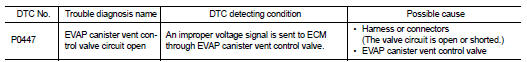
DTC CONFIRMATION PROCEDURE
1.PRECONDITIONING
If DTC Confirmation Procedure has been previously conducted, always turn ignition switch OFF and wait at least 10 seconds before conducting the next test.
TESTING CONDITION: Before performing the following procedure, confirm battery voltage is more than 11V at idle.
>> GO TO 2.
2.PERFORM DTC CONFIRMATION PROCEDURE
1. Start engine and wait at least 8 seconds.
2. Check 1st trip DTC.
Is 1st trip DTC detected? YES >> Go to EC-308, "Diagnosis Procedure".
NO >> INSPECTION END
Diagnosis Procedure
1.INSPECTION START
Do you have CONSULT-III? Do you have CONSULT-III? YES >> GO TO 2.
NO >> GO TO 3.
2.CHECK EVAP CANISTER VENT CONTROL VALVE CIRCUIT

1. Turn ignition switch OFF and then turn ON.
2. Select “VENT CONTROL/V” in “ACTIVE TEST” mode with CONSULT-III.
3. Touch “ON/OFF” on CONSULT-III screen.
4. Check for operating sound of the valve.
Clicking sound should be heard.
Is the inspection result normal?
YES >> GO TO 7.
NO >> GO TO 3.
3.CHECK EVAP CANISTER VENT CONTROL VALVE POWER SUPPLY CIRCUIT
1. Turn ignition switch OFF.
2. Disconnect EVAP canister vent control valve harness connector.
3. Turn ignition switch ON.
4. Check the voltage between EVAP canister vent control valve harness connector and ground.
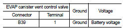
Is the inspection result normal? YES >> GO TO 5.
NO >> GO TO 4.
4.DETECT MALFUNCTIONING PART
Check the following.
• Harness connectors E11, F2
• Harness connectors E29, B10
• 15A fuse (No.42)
• Harness for open or short between EVAP canister vent control valve and IPDM E/R
>> Repair open circuit or short to ground or short to power in harness or connectors.
5.CHECK EVAP CANISTER VENT CONTROL VALVE OUTPUT SIGNAL CIRCUIT FOR OPEN AND SHORT
1. Turn ignition switch OFF.
2. Disconnect ECM harness connector.
3. Check the continuity between EVAP canister vent control valve harness connector and ECM harness connector.
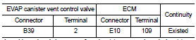
4. Also check harness for short to ground and short to power.
Is the inspection result normal? YES >> GO TO 7.
NO >> GO TO 6.
6.DETECT MALFUNCTIONING PART
Check the following.
• Junction block connector E44, E45
• Harness connectors E29, B10
• Harness for open or short between EVAP canister vent control valve and ECM
>> Repair open circuit or short to ground or short to power in harness or connectors.
7.CHECK RUBBER TUBE FOR CLOGGING
1. Disconnect rubber tube connected to EVAP canister vent control valve.
2. Check the rubber tube for clogging.
Is the inspection result normal?
YES >> GO TO 8.
NO >> Clean the rubber tube using an air blower.
8.CHECK EVAP CANISTER VENT CONTROL VALVE
Refer to EC-310, "Component Inspection".
Is the inspection result normal? YES >> GO TO 9.
NO >> Replace EVAP canister vent control valve.
9.CHECK INTERMITTENT INCIDENT
Refer to GI-42, "Intermittent Incident".
>> INSPECTION END
Component Inspection
1.CHECK EVAP CANISTER VENT CONTROL VALVE-I
1. Turn ignition switch OFF.
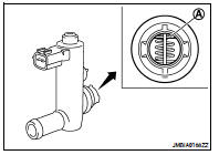
2. Remove EVAP canister vent control valve from EVAP canister.
3. Check portion (A) of EVAP canister vent control valve for being rusted.
Is it rusted? YES >> Replace EVAP canister vent control valve
NO >> GO TO 2.
2.CHECK EVAP CANISTER VENT CONTROL VALVE-II

1. Reconnect harness connectors disconnected.
2. Turn ignition switch ON.
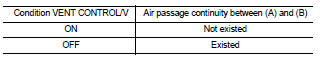
3. Perform “VENT CONTROL/V” in “ACTIVE TEST” mode.
4. Check air passage continuity and operation delay time.
Make sure new O-ring is installed properly.
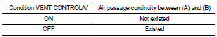
Operation takes less than 1 second.

Check air passage continuity and operation delay time under the following conditions.
Make sure new O-ring is installed properly.
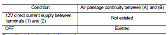
Operation takes less than 1 second.
Is the inspection result normal? YES >> INSPECTION END
NO >> GO TO 3.
3.CHECK EVAP CANISTER VENT CONTROL VALVE-III

1. Clean the air passage [portion (A) to (B)] of EVAP canister vent control valve using an air blower.
2. Perform “VENT CONTROL/V” in “ACTIVE TEST” mode.
3. Check air passage continuity and operation delay time.
Make sure new O-ring is installed properly.
Operation takes less than 1 second.

1. Clean the air passage [portion (A) to (B)] of EVAP canister vent control valve using an air blower.
2. Check air passage continuity and operation delay time under the following conditions.
Make sure new O-ring is installed properly.
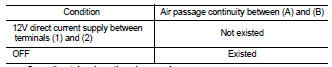
Operation takes less than 1 second.
Is the inspection result normal? YES >> INSPECTION END
NO >> Replace EVAP canister vent control valve
 P0444, p0445 evap canister purge
volume control solenoid valve
P0444, p0445 evap canister purge
volume control solenoid valve P0448 evap canister vent control
valve
P0448 evap canister vent control
valve