Nissan Altima (L32) 2007-2012 Service Manual: P1421 Cold start control
Description
ECM controls ignition timing and engine idle speed when engine is started with prewarming up condition.
This control promotes the activation of three way catalyst by heating the catalyst and reduces emissions.
DTC Logic
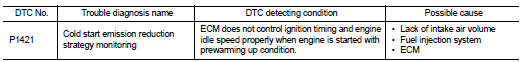
DTC DETECTION LOGIC
NOTE: If DTC P1421 is displayed with other DTC, first perform the trouble diagnosis for other DTC.
DTC CONFIRMATION PROCEDURE
1.PRECONDITIONING
If DTC Confirmation Procedure has been previously conducted, always turn ignition switch OFF and wait at least 10 seconds before conducting the next test.
TESTING CONDITION: Before performing the following procedure, confirm that battery voltage is more than 11V at idle.
>> GO TO 2.
2.PERFORM DTC CONFIRMATION PROCEDURE

1. Turn ignition switch OFF and wait at least 10 seconds.
2. Turn ignition switch ON.
3. Select “DATA MONITOR” mode with CONSULT-III.
4. Check that the “COOLAN TEMP/S” indication is between 4°C (39°F) and 36°C (97°F).
If “COOLAN TEMP/S” indication is within the specified value, go to the following step.
If “COOLAN TEMP/S” indication is out of the specified value, cool engine down or warm engine up and go to step 1.
5. Start engine and let it idle for 5 minutes.
6. Check 1st trip DTC.

Follow the procedure “With CONSULT-III” above.
Is 1st trip DTC detected? YES >> Go to EC-377, "Diagnosis Procedure".
NO >> INSPECTION END
Diagnosis Procedure
1.PERFORM IDLE AIR VOLUME LEARNING
Perform EC-30, "IDLE AIR VOLUME LEARNING : Special Repair Requirement".
Is Idle Air Volume Learning carried out successfully? YES >> GO TO 2.
NO >> Follow the instruction of Idle Air Volume Learning.
2.CHECK INTAKE SYSTEM
Check for the cause of intake air volume lacking. Refer to the following.
• Crushed intake air passage
• Intake air passage clogging
Is the inspection result normal? YES >> GO TO 3.
NO >> Repair or replace malfunctioning part
3.CHECK FUEL INJECTION SYSTEM FUNCTION
Perform DTC CONFIRMATION PROCEDURE for DTC P0171. Refer to EC-254, "DTC Logic".
Is the inspection result normal? YES >> GO TO 4.
NO >> Go to EC-255, "Diagnosis Procedure" for DTC P0171.
4.PERFORM DTC CONFIRMATION PROCEDURE

1. Turn ignition switch ON.
2. Select “SELF DIAG RESULTS” mode with CONSULT-III.
3. Touch “ERASE”.
4. Perform DTC CONFIRMATION PROCEDURE.
See EC-377, "DTC Logic".

1. Turn ignition switch ON.
2. Select Service $04 with GST.
3. Perform DTC CONFIRMATION PROCEDURE.
See EC-377, "DTC Logic".
Is the 1st trip DTC P1421 displayed again? YES >> GO TO 5.
NO >> INSPECTION END
5.REPLACE ECM
1. Replace ECM.
2. Go to EC-27, "ADDITIONAL SERVICE WHEN REPLACING CONTROL UNIT : Special Repair Requirement".
>> INSPECTION END
 P1226 TP Sensor
 P1550 battery current sensor