Nissan Altima (L32) 2007-2012 Service Manual: P2100, p2103 throttle control motor relay
Description
Power supply for the throttle control motor is provided to the ECM via throttle control motor relay. The throttle control motor relay is ON/OFF controlled by the ECM. When the ignition switch is turned ON, the ECM sends an ON signal to throttle control motor relay and battery voltage is provided to the ECM. When the ignition switch is turned OFF, the ECM sends an OFF signal to throttle control motor relay and battery voltage is not provided to the ECM.
DTC Logic
DTC DETECTION LOGIC
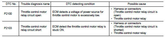
DTC CONFIRMATION PROCEDURE
1.PRECONDITIONING
If DTC Confirmation Procedure has been previously conducted, always turn ignition switch OFF and wait at least 10 seconds before conducting the next test.
TESTING CONDITION: Before performing the following procedure, confirm that battery voltage is more than 8V.
Witch DTC is detected? P2100 >> GO TO 2.
P2103 >> GO TO 3.
2.PERFORM DTC CONFIRMATION PROCEDURE FOR DTC P2100
1. Turn ignition switch ON and wait at least 2 seconds.
2. Start engine and let it idle for 5 seconds.
3. Check DTC.
Is DTC detected? YES >> Go to EC-914, "Diagnosis Procedure".
NO >> INSPECTION END
3.PERFORM DTC CONFIRMATION PROCEDURE FOR DTC P2103
1. Turn ignition switch ON and wait at least 1 second.
2. Check DTC.
Is DTC detected? YES >> Go to EC-914, "Diagnosis Procedure".
NO >> INSPECTION END
Diagnosis Procedure
1.CHECK THROTTLE CONTROL MOTOR RELAY POWER SUPPLY CIRCUIT
1. Turn ignition switch OFF.
2. Disconnect ECM harness connector.
3. Disconnect IPDM E/R harness connector F10.
4. Check the continuity between ECM harness connector and IPDM E/R harness connector.
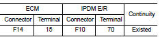
5. Also check harness for short to ground and short to power.
Is the inspection result normal? YES >> GO TO 2.
NO >> Repair open circuit or short to ground or short to power in harness or connectors.
2.CHECK THROTTLE CONTROL MOTOR RELAY INPUT SIGNAL CIRCUIT
1. Check the continuity between ECM harness connector and IPDM E/R harness connector.
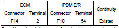
2. Also check harness for short to ground and short to power.
Is the inspection result normal? YES >> GO TO 3.
NO >> Repair open circuit or short to ground or short to power in harness or connectors.
3.CHECK FUSE
1. Disconnect 15A fuse (No. 42) from IPDM E/R.
2. Check 15A fuse for blown.
Is the inspection result normal? YES >> GO TO 4.
NO >> Replace 15A fuse.
4.CHECK INTERMITTENT INCIDENT
Refer to GI-42, "Intermittent Incident".
Is the inspection result normal? YES >> Replace IPDM E/R.
NO >> Repair or replace harness or connectors.
 P1805 brake switch
 P2101 electric throttle control
function
P2101 electric throttle control
function