Nissan Altima (L32) 2007-2012 Service Manual: Power supply and ground circuit
Description
• EPS system functions by ignition power supply.
Diagnosis Procedure
1.CHECK POWER SUPPLY
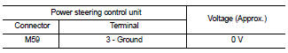
1. Turn the ignition switch OFF.
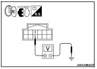
2. Disconnect power steering control unit harness connector.
3. Check voltage between power steering control unit harness connector M59 terminal 3 and ground.
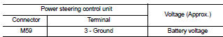
4. Turn the ignition switch ON.
CAUTION: Never start the engine.
5. Check voltage between power steering control unit harness connector M59 terminal 3 and ground.
Is the inspection result normal? YES >> GO TO 2.
NO >> Check the following. If any items are damaged, repair or replace damaged parts.
• 10A fuses (#3) open - Harness for short or open between ignition switch and power steering control unit harness connector No. 3 terminal.
- Ignition switch.
2.CHECK GROUND CIRCUIT
1. Turn the ignition switch OFF.
2. Check continuity between power steering control unit harness connector M59 terminal 6 and ground.
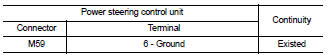
Is the inspection result normal? YES >> GO TO 3.
NO >> Repair open circuit or short to power in harness or connectors.
3.CHECK TERMINALS AND HARNESS CONNECTORS
Check power steering control unit pin terminals for damage or loose connection with harness connector.
Is the inspection result normal? YES >> Inspection End
NO >> Repair or replace damaged parts.
 Component diagnosis
 Power steering solenoid valve