Nissan Altima (L32) 2007-2012 Service Manual: Power supply and ground circuit
BCM
Diagnosis Procedure
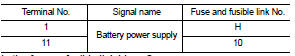
1. CHECK FUSE AND FUSIBLE LINK
Check if the following BCM fuse or fusible link are blown.
Is the fuse or fusible link blown?
YES >> Replace the blown fuse or fusible link after repairing the affected
circuit.
NO >> GO TO 2
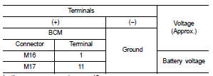
2. CHECK POWER SUPPLY CIRCUIT
1. Turn ignition switch OFF.
2. Disconnect BCM.
3. Check voltage between BCM harness connector and ground.
Is the measurement normal?
YES >> GO TO 3
NO >> Repair or replace harness.
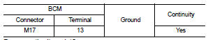
3. CHECK GROUND CIRCUIT
Check continuity between BCM harness connector and ground.
Does continuity exist?
YES >> Inspection End.
NO >> Repair or replace harness.
Special Repair Requirement
1. REQUIRED WORK WHEN REPLACING BCM
Initialize control unit. Refer to BCS-6, "CONFIGURATION (BCM) : Special
Repair Requirement".
>> Work End.
Description
BCM receives the engine status signal from ECM via CAN communication.
DTC Logic
DTC DETECTION LOGIC
NOTE:
• If DTC B26E1 is displayed with DTC U1000, first perform the trouble dia ...
Diagnosis Procedure
1. CHECK FUSES AND FUSIBLE LINK
Check that the following IPDM E/R fuses or fusible link are not blown.
Is the fuse blown?
YES >> Replace the blown fuse or fusible ...
Other materials: I-FCW system operation
For vehicles with the 7 inch (18 cm) display
Vehicle ahead detection indicator
AEB with Pedestrian Detection system
warning light
For vehicles with the 5 inch (13 cm) display
The I-FCW system operates at speeds
above approximately 3 mph (5 km/h).
If there is a potential risk of a forward co ...
Operating ProPILOT Assist
Push the ProPILOT Assist switch A. This
turns on the ProPILOT Assist system.
A screen is displayed for a period of time
that indicates the status of the driving
aid functions.
AEB with Pedestrian Detection, LDW,
and BSW are enabled when the specified
driving aid is shaded.
I-LI is ...
Spark plugs
Replacing spark plugs
Iridium-tipped spark plugs
It is not necessary to replace iridium-tipped A
spark plugs as frequently as conventional
type spark plugs because they
last much longer. Follow the maintenance
log shown in the "Maintenance and schedules"
section of this manual. Do not service
iridi ...
 B26e1 no reception of engine status signal
 IPDM E/R (Intelligent power distribution module engine room)