Nissan Altima (L32) 2007-2012 Service Manual: Precaution
Precaution for Supplemental Restraint System (SRS) "AIR BAG" and "SEAT BELT PRE-TENSIONER" The Supplemental Restraint System such as “AIR BAG” and “SEAT BELT PRE-TENSIONER”, used along with a front seat belt, helps to reduce the risk or severity of injury to the driver and front passenger for certain types of collision. This system includes seat belt switch inputs and dual stage front air bag modules. The SRS system uses the seat belt switches to determine the front air bag deployment, and may only deploy one front air bag, depending on the severity of a collision and whether the front occupants are belted or unbelted.
Information necessary to service the system safely is included in the SR and SB section of this Service Manual.
WARNING: • To avoid rendering the SRS inoperative, which could increase the risk of personal injury or death in the event of a collision which would result in air bag inflation, all maintenance must be performed by an authorized NISSAN/INFINITI dealer.
• Improper maintenance, including incorrect removal and installation of the SRS, can lead to personal injury caused by unintentional activation of the system. For removal of Spiral Cable and Air Bag Module, see the SR section.
• Do not use electrical test equipment on any circuit related to the SRS unless instructed to in this Service Manual. SRS wiring harnesses can be identified by yellow and/or orange harnesses or harness connectors.
Precaution for Procedure without Cowl Top Cover
When performing the procedure after removing cowl top cover, cover the lower end of windshield with urethane, etc.
Precaution Necessary for Steering Wheel Rotation After Battery Disconnect
NOTE: • This Procedure is applied only to models with Intelligent Key system and NVIS/IVIS (NISSAN/INFINITI VEHICLE IMMOBILIZER SYSTEM - NATS).
• Remove and install all control units after disconnecting both battery cables with the ignition knob in the ″LOCK″ position.
• Always use CONSULT-III to perform self-diagnosis as a part of each function inspection after finishing work.
If DTC is detected, perform trouble diagnosis according to self-diagnostic results.
For models equipped with the Intelligent Key system and NVIS/IVIS, an electrically controlled steering lock mechanism is adopted on the key cylinder.
For this reason, if the battery is disconnected or if the battery is discharged, the steering wheel will lock and steering wheel rotation will become impossible.
If steering wheel rotation is required when battery power is interrupted, follow the procedure below before starting the repair operation.
OPERATION PROCEDURE
1. Connect both battery cables.
NOTE: Supply power using jumper cables if battery is discharged.
2. Use the Intelligent Key or mechanical key to turn the ignition switch to the ″ACC″ position. At this time, the steering lock will be released.
3. Disconnect both battery cables. The steering lock will remain released and the steering wheel can be rotated.
4. Perform the necessary repair operation.
5. When the repair work is completed, return the ignition switch to the ″LOCK″ position before connecting the battery cables. (At this time, the steering lock mechanism will engage.) 6. Perform a self-diagnosis check of all control units using CONSULT-III.
Precaution for On Board Diagnosis (OBD) System of CVT and Engine
The ECM has an on board diagnostic system. It will light up the malfunction indicator lamp (MIL) to warn the driver of a malfunction causing emission deterioration.
CAUTION: • Be sure to turn the ignition switch OFF and disconnect the battery cable from the negative terminal before any repair or inspection work. The open/short circuit of related switches, sensors, solenoid valves, etc. will cause the MIL to light up.
• Be sure to connect and lock the connectors securely after work. A loose (unlocked) connector will cause the MIL to light up due to an open circuit. (Be sure the connector is free from water, grease, dirt, bent terminals, etc.) • Be sure to route and secure the harnesses properly after work. Interference of the harness with a bracket, etc. may cause the MIL to light up due to a short circuit.
• Be sure to connect rubber tubes properly after work. A misconnected or disconnected rubber tube may cause the MIL to light up due to a malfunction of the EVAP system or fuel injection system, etc.
• Be sure to erase the unnecessary malfunction information (repairs completed) from the TCM and ECM before returning the vehicle to the customer.
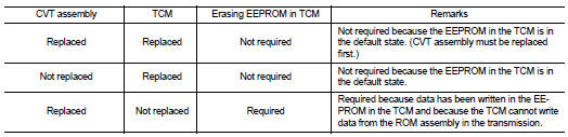
Precaution for TCM and CVT Assembly Replacement
CAUTION: • Check if new data (Unit ID) are entered correctly after replacing CVT assembly and erasing data in TCM. (Connect CONSULT-III, and then turn ignition switch OFF.) • When replacing CVT assembly or TCM, refer to the pattern table below and erase the EEPROM in the TCM if necessary.
EEPROM ERASING PATTERNS
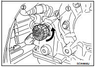
Removal and Installation Procedure for CVT Unit Connector
REMOVAL
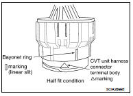
Rotate bayonet ring (1) counterclockwise, pull out CVT unit harness connector (2) and remove it.
INSTALLATION
1. Align Δ marking on CVT unit harness connector terminal body
with  marking on bayonet ring,
insert CVT unit harness connector,
and then rotate bayonet ring clockwise.
marking on bayonet ring,
insert CVT unit harness connector,
and then rotate bayonet ring clockwise.
2. Rotate bayonet ring clockwise until Δ marking on CVT unit harness connector terminal body is aligned with the slit on bayonet ring as shown in the figure (correctly fitting condition), install CVT unit harness connector to CVT unit harness connector terminal body.
CAUTION: • Securely align Δ marking on CVT unit harness connector terminal body with bayonet ring slit. Then, be careful not to make a half fit condition as shown in the figure.
• Do not mistake the slit of bayonet ring for other dent portion.
Precaution
NOTE: If any malfunction occurs in the RE0F10A model transaxle, replace the entire transaxle assembly.
• Before connecting or disconnecting the TCM harness connector, turn ignition switch OFF and disconnect negative battery cable.
Because battery voltage is applied to TCM even if ignition switch is turned OFF.
• When connecting or disconnecting pin connectors into or from TCM, take care not to damage pin terminals (bend or break).
When connecting pin connectors make sure that there are not any bends or breaks on TCM pin terminal.
• Before replacing TCM, perform TCM input/output signal inspection and make sure whether TCM functions properly or not. TM-375, "Reference Value".
• After performing each TROUBLE DIAGNOSIS, perform “DTC CONFIRMATION PROCEDURE”.
If the repair is completed the DTC should not be displayed in the “DTC CONFIRMATION PROCEDURE”.
• Always use the specified brand of CVT fluid. Refer to MA-12, "Fluids and Lubricants".
• Use lint-free paper, not cloth rags, during work.
• After replacing the CVT fluid, dispose of the waste oil using the methods prescribed by law, ordinance, etc.
Service Notice or Precaution
CVT FLUID COOLER SERVICE
If CVT fluid contains friction material (clutches, brakes, etc.), or if a CVT is replaced, inspect and clean the CVT fluid cooler mounted in the radiator or replace the radiator. Flush cooler lines using cleaning solvent and compressed air after repair. For CVT fluid cooler cleaning procedure, refer to TM-418, "Cleaning". For radiator replacement, refer to CO-15, "Removal and Installation".
OBD-II SELF-DIAGNOSIS
• CVT self-diagnosis is performed by the TCM in combination with the ECM. The results can be read through the blinking pattern of the malfunction indicator lamp (MIL). Refer to the table on TM-298, "CONSULT-III Function (TRANSMISSION)" for the indicator used to display each self-diagnostic result.
• The self-diagnostic results indicated by the MIL are automatically stored in both the ECM and TCM memories.
Always perform the procedure on TM-296, "Diagnosis Description" to complete the repair and avoid unnecessary blinking of the MIL.
For details of OBD-II, refer to EC-112, "Diagnosis Description" (for California), EC-641, "Diagnosis Description" (except for California).
• Certain systems and components, especially those related to OBD, may use the new style slide-locking type harness connector. For description and how to disconnect, refer to PG-58, "Description" (Coupe) or PG-129, "Description" (Sedan).
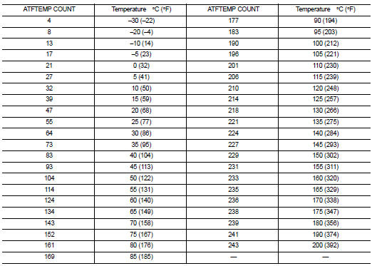
ATFTEMP COUNT Conversion Table
 Symptom diagnosis
 Preparation