Nissan Altima (L32) 2007-2012 Service Manual: Removal and installation
TRANSAXLE ASSEMBLY
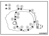
Exploded View
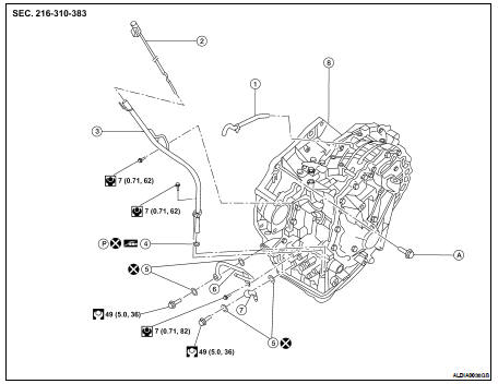
1. Air breather hose
2. CVT fluid level gauge
3. CVT fluid charging pipe
4. O-ring
5. Copper washer
6. Fluid cooler tube
7. Fluid cooler tube
8. CVT assembly
A. Refer to TM-447, "Removal and Installation".
Removal and Installation
REMOVAL
1. Remove the engine and transaxle as an assembly. Refer to EM-72, "Removal and Installation".
NOTE: Using paint, put matching marks on the drive plate and torque converter when removing the torque converter to drive plate nuts.
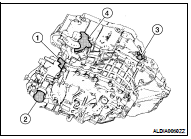
2. Disconnect the electrical connectors from the following: • Primary speed sensor (1) • Secondary speed sensor (3) • CVT unit connector (2) • PNP switch (4) 3. Remove the harness from the CVT.
4. Remove the CVT to engine and engine to CVT bolts.
5. Separate the CVT from the engine.
6. If necessary, remove the following from the CVT: • Primary speed sensor
• Secondary speed sensor
• PNP switch
• CVT fluid charging pipe
• Water tube and hoses
• Air breather hose
• Any necessary brackets
INSTALLATION
Installation is in the reverse order of removal.
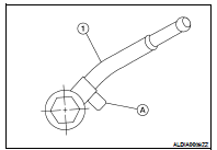
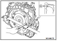
CAUTION: • When installing fluid cooler tube align the tube (1) against the rib (2) as shown.
• When replacing an engine or transaxle you must make sure any dowels are installed correctly during re-assembly.
• Improper alignment caused by missing dowels may cause vibration, oil leaks or breakage of drivetrain components.
• Do not reuse O-rings.
• When turning crankshaft, turn it clockwise as viewed from the front of the engine.
• When tightening the nuts for the torque converter while securing the crankshaft pulley bolt, be sure to confirm the tightening torque of the crankshaft pulley bolt. Refer to EM- 52, "Removal and Installation".
• After converter is installed to drive plate, rotate crankshaft several turns to check that CVT rotates freely without binding.
• When installing the CVT to the engine, align the matching mark on the drive plate with the matching mark on the torque converter.
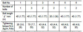
When installing the CVT to the engine, attach the bolts in accordance with the following standard.
• A : Transaxle assembly to engine assembly.
• B : Engine assembly to transaxle assembly.
• When installing the drive plate to torque converter nuts, tighten them temporarily. then tighten the nuts to the specified torque.
• After completing installation, check for fluid leakage, fluid level, and the positions of CVT. Refer to TM-416, "Inspection" and TM-429, "Inspection and Adjustment".
• When replacing the CVT assembly, erase EEP ROM in TCM.
Inspection
Installation and Inspection of Torque Converter
• After installing the torque converter to the CVT, be sure to check distance “A” to ensure it is within specifications.
Distance "A" : 14.4 mm (0.567 in)
 Control valve
 Disassembly and assembly