Nissan Altima (L32) 2007-2012 Service Manual: Replacement operations
Description
This section is prepared for technicians who have attained a high level of skill and experience in repairing collision- damaged vehicles and also use modern service tools and equipment. Persons unfamiliar with body repair techniques should not attempt to repair collision-damaged vehicles by using this section.
Technicians are also encouraged to read Body Repair Manual (Fundamentals) in order to ensure that the original functions and quality of the vehicle can be maintained. The Body Repair Manual (Fundamentals) contains additional information, including cautions and warning, that are not including in this manual. Technicians should refer to both manuals to ensure proper repairs.
Please note that these information are prepared for worldwide usage, and as such, certain procedures might not apply in some regions or countries.
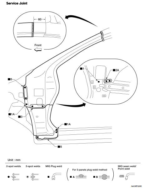
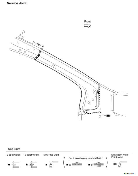
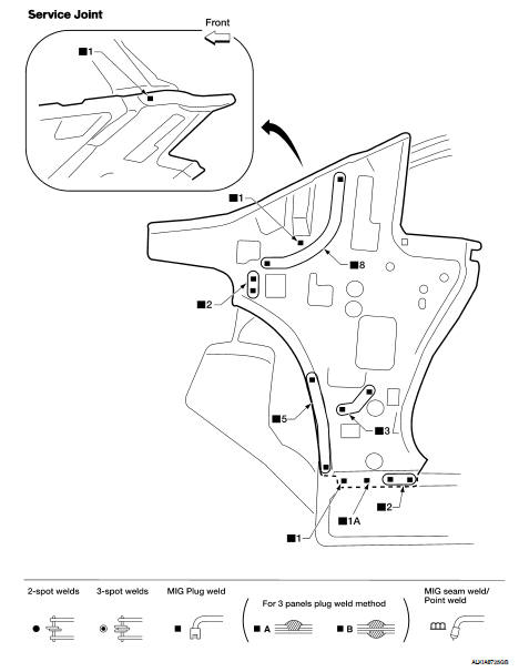
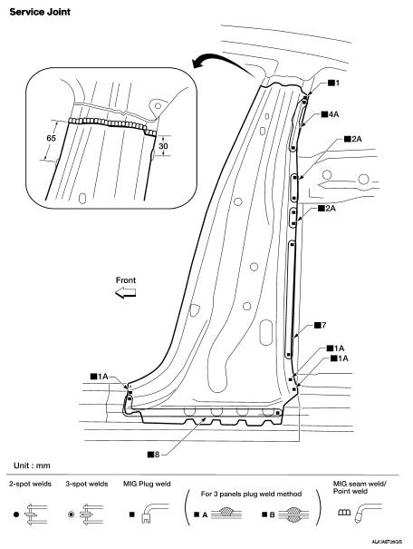
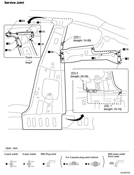
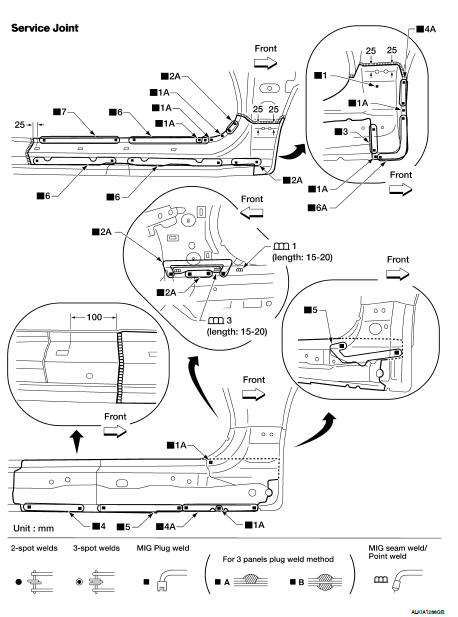
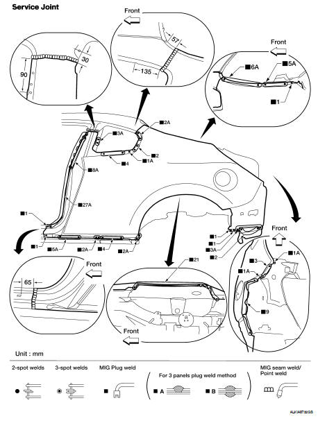
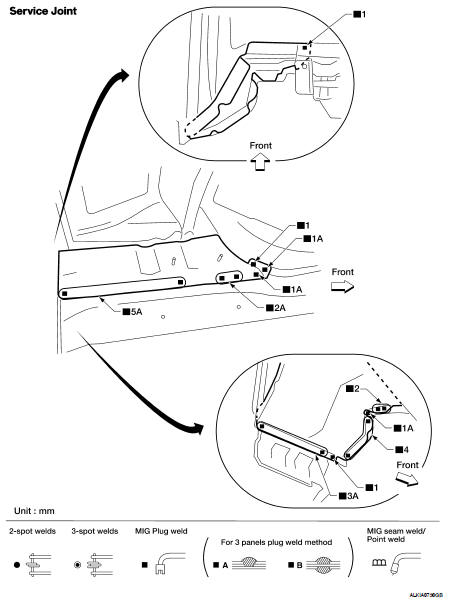
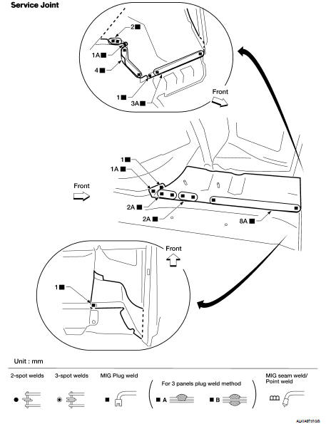
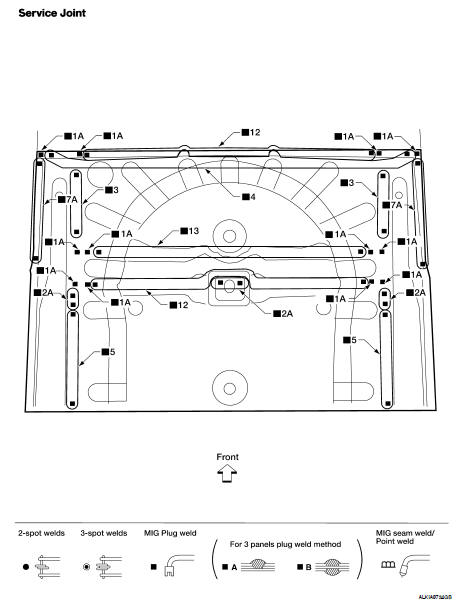
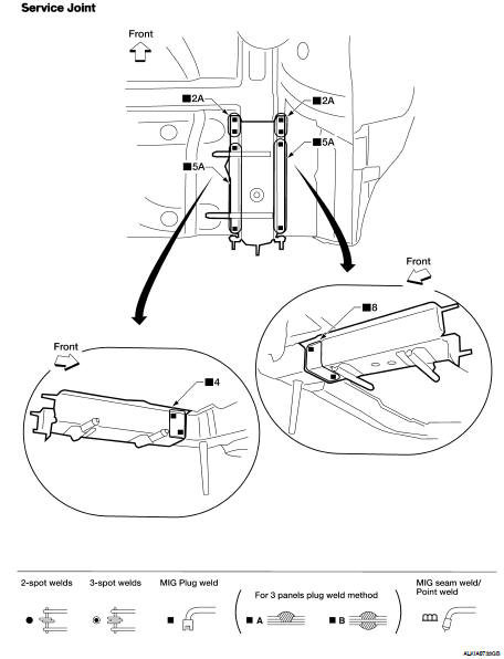
The symbols used in this section for cutting and welding / brazing operations are shown below.
• Front pillar butt joint can be determined anywhere within shaded area as shown in the figure. The best location for the butt joint is at position A due to the construction of the vehicle. Refer to the front pillar section.
• Determine cutting position and record distance from the locating indent. Use this distance when cutting the service part. Cut outer front pillar over 60 mm above inner front pillar cut position.
• Prepare a cutting jig to make outer pillar easier to cut. Also, this will permit service part to be accurately cut at joint position.
• An example of cutting operation using a cutting jig is as follows.
1. Mark cutting lines.
A: Cut position of outer pillar
B: Cut position of inner pillar
2. Align cutting line with notch on jig. Clamp jig to pillar.
3. Cut outer pillar along groove of jig. (At position A) 4. Remove jig and cut remaining portions.
5. Cut inner pillar at position B in same manner.
Hoodledge
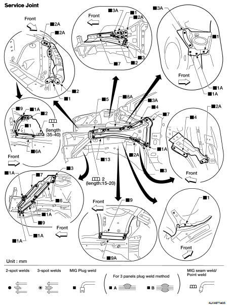
Change parts
● Front strut housing (LH)
● Upper front hoodledge
● Hoodledge reinforcement
● Hoodledge connector
● Radiator core support upper
● Hoodledge reinforcement rear
Front Side Member Front Assembly
• Work after the hoodledge has been removed.
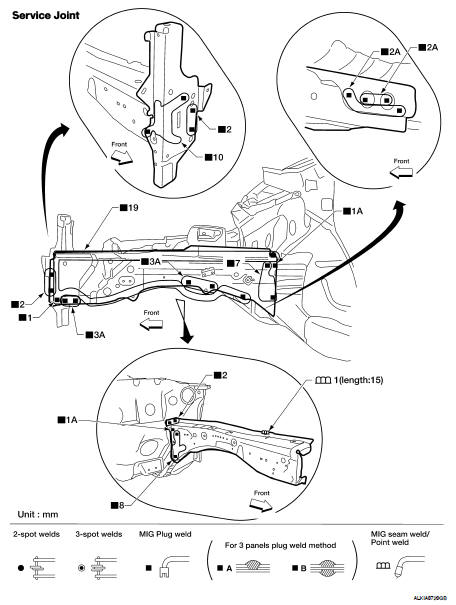
Change parts
● Front side member front assembly
● Front side member front closing plate
● Radiator core side support
Front Side Member
• Work after front side member front assembly has been removed.
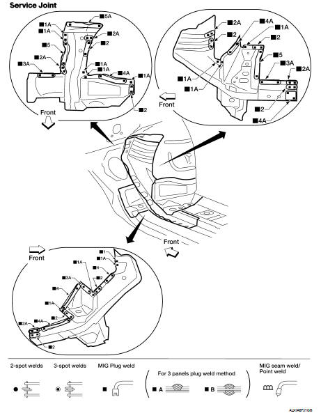
Change parts
● Front side member assembly
Front Pillar
OUTER
• Work after the hoodledge and hoodledge reinforcement rear have been removed.
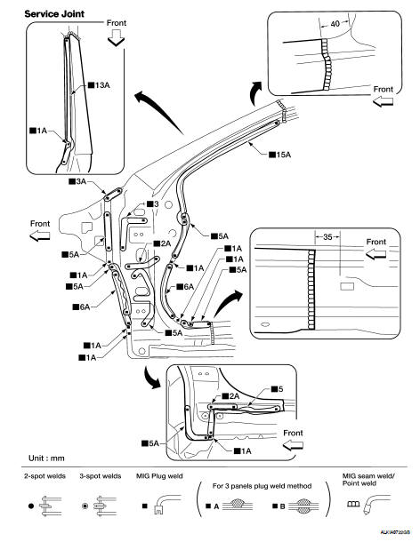
Change parts
● Front pillar section of body side outer
REINFORCEMENT
• Work after the front pillar section of the body side outer has been removed.
Change parts
● Hinge pillar upper reinforcement
● Hinge pillar lower reinforcement
INNER
• Work after the hinge pillar upper and lower reinforcements have been removed.
Change parts
● Front pillar inner reinforcement
Dash Side
Work with the front pillar inner reinforcement removed.
Change parts
● Dash side
Center Pillar
REINFORCEMENT
Work after the rear fender has been removed.
Change parts
● Lock pillar reinforcement
INNER
Work after the lock pillar reinforcement and outer sill have been removed.
Change parts
● Lock pillar inner
● Rear pillar inner
Outer Sill Reinforcement
Work after the front pillar lower reinforcement and lock pillar reinforcement have been removed.
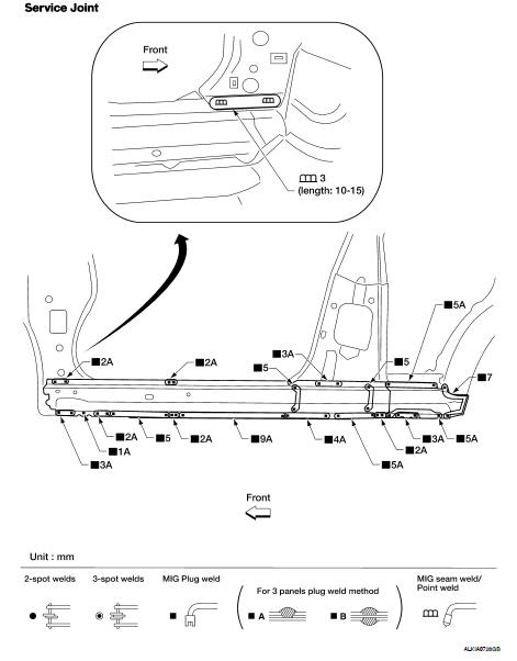
Change parts
● Outer sill reinforcement
Sill Partial
Change parts
● Sill portion of body side outer
● Front portion of outer sill reinforcement
Rear Fender
• The rear panel assembly to rear fender welds must be separated prior to removal.
Change parts
● Rear fender
Rear Panel
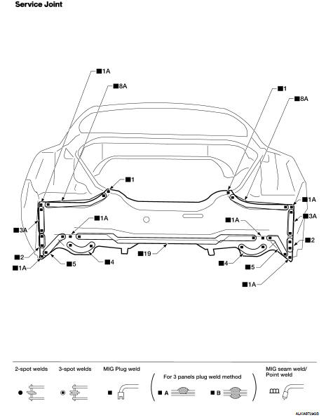
Change parts
● Rear panel assembly
Rear Floor Rear LH
• Work after rear panel assembly has been removed.
Change parts
● Rear floor rear LH
Rear Floor Rear RH
• Work after rear panel assembly has been removed.
Change parts
● Rear floor rear RH
Rear Floor Rear
• Work after rear panel assembly, rear floor rear LH, and rear floor rear RH have been removed.
Change parts
● Rear floor rear
Rear Side Member Extension
• Work after rear panel assembly has been removed.
Change parts
● Rear side member extension
Foam Repair
During factory assembly, foam insulators are installed in certain body panels and locations around the vehicle.
Use the following procedure(s) to replace any factory-installed foam insulators.
URETHANE FOAM APPLICATIONS
Use commercially available spray for sealant (foam material) repair of material used on vehicle. Read instructions on product for fill procedures.
FILL PROCEDURES
1. Fill procedures after installation service part.
• Remove foam material remaining on vehicle side.
• Clean area in which foam was removed.
• Install service part.
• Insert nozzle into hole near fill area and fill foam material or fill in enough to close gap with service part.
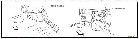
2. Fill procedures before installation service part • Remove foam material remaining on vehicle side.
• Clean area in which foam material on wheelhouse outer side.
NOTE: Fill in enough to close gap with service part while avoiding flange area.
• Install service part.
NOTE: Refer to label for information on working times.
1. Body side outer
2. Body side insulation (expanding foam baffle) upper front pillar
3. Body side insulation (expanding foam tape) front pillar
4. Roof panel assembly
5. Roof panel insulation (expanding foam baffle) front roof rail
6. Body side insulation (expanding foam tape) rear pillar
7. Body side insulation (expanding foam baffle) roof side
8. Body side insulation (expanding foam tape) lock pillar upper
9. 9.Body side insulation (expanding foam baffle) lock pillar upper
10. Body side insulation (expanding foam tape) upper rear pillar
11. Body side insulation (expanding foam tape) inner upper rear pillar
12. Body side insulation (expanding foam tape) hinge pillar lower
13. body side insulation (expanding foam tape) lock pillar lower
14. Body side insulation (expanding foam tape) rear wheel well
 Precautions in repairing high
strength steel
Precautions in repairing high
strength steel Body repair sedan