Nissan Altima (L32) 2007-2012 Service Manual: Road test
Description
DESCRIPTION
• The purpose of the test is to determine overall performance of CVT and analyze causes of problems.
• The road test consists of the following three parts: 1. “Check Before Engine Is Started” TM-249.
2. “Check at Idle” TM-250.
3. “Cruise Test” TM-251.
• Before road test, familiarize yourself with all test procedures and items to check.
• Perform tests on all items until specified symptom is found. Troubleshoot items which check out No Good after road test.
CONSULT-III SETTING PROCEDURE
• Using CONSULT-III, perform a cruise test and record the result.
• Print the result and ensure that shifts and lock-ups take place as per Shift Schedule.
1. Touch “DATA MONITOR” on “SELECT DIAG MODE” screen.
2. Touch “MAIN SIGNALS” to set recording condition.
3. See “Numerical Display”, “Barchart Display” or “Line Graph Display”.
4. Touch “START”.
5. When performing cruise test. Refer to TM-251, "Cruise Test".
6. After finishing cruise test part, touch “RECORD”.
7. Touch “STORE”.
8. Touch “BACK”.
9. Touch “DISPLAY”.
10. Touch “PRINT”.
11. Check the monitor data printed out.
Check before Engine Is Started
1.CHECK CVT INDICATOR LAMP
1. Park vehicle on flat surface.
2. Move selector lever to “P” position.
3. Turn ignition switch OFF. Wait at least 5 seconds.
4. Turn ignition switch ON. (Do not start engine.) Does shift position indicator come on for about 2 seconds? YES >> 1. Turn ignition switch OFF.
2. Perform self-diagnosis and note NG items.
Refer to TM-119, "CONSULT-III Function (TRANSMISSION)".
3. Go to TM-250, "Check at Idle".
NO >> Stop “Road Test”. Refer to TM-222, "Symptom Table".
Check at Idle
1.CHECK STARTING THE ENGINE
1. Park vehicle on flat surface.
2. Move selector lever to “P” or “N” position.
3. Turn ignition switch OFF.
4. Turn ignition switch to “START” position.
Is engine started? YES >> GO TO 2.
NO >> Stop “Road Test”. Refer to TM-222, "Symptom Table".
2.CHECK STARTING THE ENGINE
1. Turn ignition switch ON.
2. Move selector lever to “D”, “M” or “R” position.
3. Turn ignition switch to “START” position.
Is engine started? YES >> Stop “Road Test”. Refer to TM-222, "Symptom Table".
NO >> GO TO 3.
3.CHECK “P” POSITION FUNCTION
1. Move selector lever to “P” position.
2. Turn ignition switch OFF.
3. Release parking brake.
4. Push vehicle forward or backward.
5. Apply parking brake.
Does vehicle move when it is pushed forward or backward? YES >> Refer to TM-222, "Symptom Table". Continue “Road Test”.
NO >> GO TO 4.
4.CHECK “N” POSITION FUNCTION
1. Start engine.
2. Move selector lever to “N” position.
3. Release parking brake.
Does vehicle move forward or backward? YES >> Refer to TM-222, "Symptom Table". Continue “Road Test”.
NO >> GO TO 5.
5.CHECK SHIFT SHOCK
1. Apply foot brake.
2. Move selector lever to “R” position.
Is there large shock when changing from “N” to “R” position? YES >> Refer to TM-222, "Symptom Table". Continue “Road Test”.
NO >> GO TO 6.
6.CHECK “R” POSITION FUNCTION
Release foot brake for several seconds.
Does vehicle creep backward when foot brake is released? YES >> GO TO 7.
NO >> Refer toTM-222, "Symptom Table". Continue “Road Test”.
7.CHECK “D” POSITION FUNCTION
Move selector lever to “D” position and check if vehicle creeps forward.
Does vehicle creep forward in all positions? YES >> Go to TM-251, "Cruise Test".
NO >> Stop “Road Test”. Refer to TM-222, "Symptom Table".
Cruise Test
1.CHECK VEHICLE SPEED WHEN SHIFTING GEARS — PART 1
1. Drive vehicle for approximately 10 minutes to warm engine oil and CVT fluid up to operating temperature.
CVT fluid operating temperature: 50 – 80°C (122 – 176°F)
2. Park vehicle on flat surface.
3. Move selector lever to “P” position.
4. Start engine.
5. Move selector lever to “D” position.
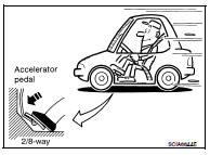
6. Accelerate vehicle to 2/8-way throttle depressing accelerator pedal constantly.
Read vehicle speed and engine speed. Refer to TM-261, "Vehicle Speed When Shifting Gears"
OK or NG
OK >> GO TO 2.
NG >> Refer to TM-222, "Symptom Table". Continue “Road Test”.
2.CHECK VEHICLE SPEED WHEN SHIFTING GEARS — PART 2
1. Park vehicle on flat surface.
2. Move selector lever to “D” position.
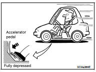
3. Accelerate vehicle to full depression depressing accelerator pedal constantly.

OK or NG
OK >> GO TO 3.
NG >> Refer to TM-222, "Symptom Table". Continue “Road Test”.
3.CHECK MANUAL MODE FUNCTION
Move to manual mode from “D” position.
Does it switch to manual mode? YES >> GO TO 4.
NO >> Refer to TM-222, "Symptom Table". Continue “Road Test”.
4.CHECK SHIFT-UP FUNCTION
During manual mode driving, is upshift from M1 → M2 → M3 → M4 → M5 → M6 performed?

Is upshifting correctly performed? YES >> GO TO 5.
NO >> Refer to TM-222, "Symptom Table". Continue “Road Test”.
5.CHECK SHIFT-DOWN FUNCTION
During manual mode driving, is downshift from M6 → M5 → M4 → M3 → M2 → M1 performed?

Is downshifting correctly performed? YES >> GO TO 6.
NO >> Refer to TM-222, "Symptom Table". Continue “Road Test”.
6.CHECK ENGINE BRAKE FUNCTION
Check engine brake.
Does engine braking effectively reduce speed in M1 position? YES >> 1. Stop the vehicle.
2. Perform self-diagnosis. Refer to TM-119, "CONSULT-III Function (TRANSMISSION)".
NO >> Refer to TM-222, "Symptom Table". then continue trouble diagnosis.
 Line pressure test
 CVT Position