Nissan Altima (L32) 2007-2012 Service Manual: Rocker cover
Exploded View
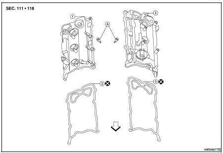
1. Rocker cover (RH)
2. Rocker cover gasket (RH)
3. Rocker cover gasket (LH)
4. Rocker cover (LH)
A. Follow installation procedure

Removal and Installation LH
REMOVAL
1. Remove the engine cover, using power tool.
2. Remove front air duct.
3. Remove blow by hose from rocker cover.
4. Remove camshaft position sensor.
CAUTION: • Handle carefully to avoid dropping and shocks.
• Do not disassemble.
• Do not allow metal powder to adhere to magnetic part at sensor tip (A).
• Do not place sensors in a location where they are exposed to magnetism.
5. Disconnect the ignition coil connectors.
6. Remove the ignition coils. Refer to EM-145, "Removal and Installation LH".
CAUTION: Never shock ignition coils.
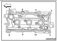
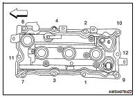
7. Remove LH rocker cover bolts from cylinder head as shown.

INSTALLATION
Installation is in the reverse order of removal.
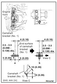
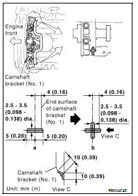
• Apply sealant to the areas on the front corners using Tool.
• Use Genuine Silicone RTV Sealant or equivalent. Refer to GI-15, "Recommended Chemical Products and Sealants".
Tool number : WS39930000 ( — )
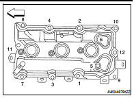
• Tighten the rocker cover bolts in two steps in the order as shown.
Removal and Installation RH
REMOVAL
1. Remove the engine cover, using power tool.
2. Disconnect the mass air flow sensor electrical connector and remove the air cleaner assembly and air intake tubes. Refer to EM-129, "Removal and Installation".
3. Remove the intake manifold collector using power tool. Remove gasket and the electric throttle control actuator. Refer to EM-130, "Removal and Installation".
4. Remove ignition coils. Refer to EM-145, "Removal and Installation RH".
CAUTION: Never shock ignition coils.
5. Remove camshaft position sensor.
CAUTION: • Handle carefully to avoid dropping and shocks.
• Do not disassemble.
• Do not allow metal powder to adhere to magnetic part at sensor tip (A).
• Do not place sensors in a location where they are exposed to magnetism.
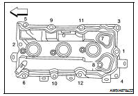
6. Remove RH rocker cover bolts from cylinder head as shown.

INSTALLATION
Installation is in the reverse order of removal.
• Apply sealant to the areas on the front corners using Tool.
• Use Genuine Silicone RTV Sealant or equivalent. Refer to GI-15, "Recommended Chemical Products and Sealants".
Tool number : WS39930000 ( — )
• Tighten the rocker cover bolts in two steps in the order as shown.
 Fuel injector and fuel tube
 Front timing chain case