Nissan Altima (L32) 2007-2012 Service Manual: Satellite radio tuner
Removal and Installation - Coupe
REMOVAL
1. Disconnect the battery negative terminal.
2. Remove the trunk floor carpet and spare tire cover. Refer to INT-23, "Removal
and Installation".
3. Remove the LH trunk floor spacer.
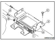
4. Remove the satellite radio tuner assembly nuts (B), and satellite
radio tuner screw (C), disconnect the satellite radio tuner harness
connectors and remove the satellite radio tuner and
bracket assembly (1 and 2), then remove the satellite radio tuner
screws (A) and remove satellite radio tuner (1) from the bracket
(2).
INSTALLATION
Installation is in the reverse order of removal.
Removal and Installation - Sedan
REMOVAL
1. Disconnect the battery negative terminal.
2. Remove the rear parcel shelf finisher. Refer to INT-38, "Removal and
Installation".
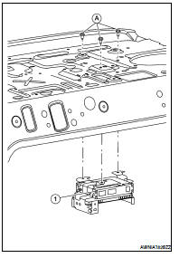
3. Remove the satellite radio tuner unit screws (A), disconnect the
satellite tuner harness connectors and remove the satellite radio
tuner (1).
Removal and Installation - Coupe
REMOVAL
1. Remove the trunk front finisher. Refer to INT-23, "Removal and
Installation".
2. Remove the rear speaker screws (A), then disconnect the r ...
Removal and Installation
REMOVAL
1. Lower the headliner at the rear. Refer to INT-20, "Removal and
Installation" (coupe) and INT-42,
"Removal and Installation" (sedan).
2. ...
 Rear speaker
 Satellite radio antenna