Nissan Altima (L32) 2007-2012 Service Manual: Self-diagnosis function
Diagnosis Description
SELF-DIAGNOSIS SYSTEM
The self-diagnosis system is built into the front air control to quickly locate the cause of malfunctions.
SELF-DIAGNOSIS FUNCTION
The self-diagnosis system diagnoses sensors, door motors, blower motor, etc. by system line. Refer to applicable sections (items) for details. Shifting from normal control to the self-diagnosis system is accomplished by starting the engine (pressing the ignition switch to the ON position) and pressing OFF switch for at least 5 seconds.
The OFF switch must be pressed within 10 seconds after starting the engine (ignition switch is pressed to the ON position). This system will be canceled by either pressing AUTO switch or pressing the ignition switch OFF. Shifting from one step is accomplished by means of turning temperature control dial (LH side), as required.
Shifting from STEP-5 to AUXILIARY MECHANISM is accomplished by turning the LH temperature control dial clockwise or counterclockwise.
CONFIRMATION METHOD
1.SET IN SELF-DIAGNOSIS MODE
1. Press ignition switch ON.
2. Set in self-diagnosis mode as follows. Within 10 seconds after starting engine (ignition switch is pressed ON.), press OFF switch for at least 5 seconds.
NOTE:
• If battery voltage drops below 12 V during diagnosis STEP-3, door motor speed becomes slower and as a result, the system may generate an error even when operation is normal. To avoid this, start engine before performing this diagnosis.
• Former STEP-1 (LEDs and display screen are checked) does not exist in this self-diagnosis function.
>> GO TO 2
2.STEP-2: SENSOR CIRCUITS ARE CHECKED FOR OPEN OR SHORT CIRCUIT
Does code No. 20 appear on the display? YES >> GO TO 3
NO >> GO TO 12
3.CHECK TO ADVANCE SELF-DIAGNOSIS STEP-3
Turn temperature control dial (LH) clockwise.
Advance to self-diagnosis STEP-3? YES >> GO TO 4
NO >> Replace front air control. (Temperature control dial is malfunctioning.) Refer to VTL-8, "Removal and Installation".
4.CHECK TO RETURN SELF-DIAGNOSIS STEP-2
Turn temperature control dial (LH) counterclockwise.
Return to self-diagnosis STEP-2? YES >> GO TO 5
NO >> Malfunctioning front air control. Refer to VTL-8, "Removal and Installation".
5.STEP-3: MODE DOOR AND INTAKE DOOR POSITIONS ARE CHECKED
Turn temperature control dial (LH) clockwise.
Does code No. 30 appear on the display? YES >> GO TO 6
NO >> GO TO 13
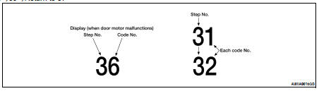
6.STEP-4: OPERATION OF EACH DOOR MOTOR IS CHECKED
1. Turn temperature control dial (LH side) clockwise.
2. Press  (DEF) switch. Code No. of
each door motor test is
indicated on the display.
(DEF) switch. Code No. of
each door motor test is
indicated on the display.
>> GO TO 7
7.CHECK ACTUATORS
Refer to the following chart and check discharge air flow, air temperature, blower motor duty ratio and compressor operation.
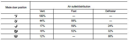
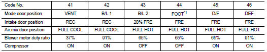
Checks must be made visually, by listening to the sound, or by touching air outlets with hand, etc. for improper operation.
*1: FOOT position during automatic control. Refer to HAC-5, "Description and Conditions".
Is the inspection result normal? YES >> GO TO 8
NO >> • Air outlet does not change.
Go to Mode Door Motor Circuit. Refer to HAC-32, "Diagnosis Procedure".
• Discharge air temperature does not change.
Go to Air Mix Door Motor Circuit. Refer to HAC-35, "Diagnosis Procedure".
• Intake door does not change.
Go to Intake Door Motor Circuit. Refer to HAC-38, "Diagnosis Procedure".
• Blower motor operation is malfunctioning.
Go to Blower Motor Circuit. Refer to HAC-42, "Diagnosis Procedure".
• Magnet clutch does not engage.
Go to Magnet Clutch Circuit. Refer to HAC-47, "Diagnosis Procedure".
8.STEP-5: TEMPERATURE OF EACH SENSOR IS CHECKED
1. Turn temperature control dial (LH) clockwise.
2. Code No. 51 appears on the display.
>> GO TO 9
9.CHECK AMBIENT SENSOR
Press  (DEF) switch one time.
Temperature detected by ambient
sensor is indicated on the display.
(DEF) switch one time.
Temperature detected by ambient
sensor is indicated on the display.
NOTE: If the temperature indicated on the display greatly differs from the actual temperature, check sensor circuit first, and then check sensor.
Is the inspection result normal? YES >> GO TO 10 NO >> Go to Ambient Sensor Circuit. Refer to HAC-50, "Diagnosis Procedure".
10.CHECK IN-VEHICLE SENSOR
Press  (DEF) switch for the
second time. Temperature detected
by in-vehicle sensor is indicated on the display.
(DEF) switch for the
second time. Temperature detected
by in-vehicle sensor is indicated on the display.
NOTE: If the temperature indicated on the display greatly differs from the actual temperature, check sensor circuit first, and then check sensor.
Is the inspection result normal? YES >> GO TO 11
NO >> Go to In-vehicle Sensor Circuit. Refer to HAC-53, "Diagnosis Procedure".
11.CHECK INTAKE SENSOR
Press (DEF) switch for the third
time. Temperature detected by
intake sensor is indicated on the display.
(DEF) switch for the third
time. Temperature detected by
intake sensor is indicated on the display.
NOTE: If the temperature indicated on the display greatly differs from the actual temperature, check sensor circuit first, and then check sensor.
Is the inspection result normal? YES >> GO TO 12
NO >> Go to Intake Sensor Circuit. Refer to HAC-59, "Diagnosis Procedure".
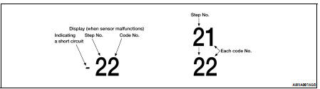
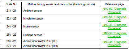
12.CHECK MALFUNCTIONING SENSOR AND DOOR MOTOR
Refer to the following chart for malfunctioning code No.
(If two or more sensors and door motors malfunction, corresponding code Nos. indicates 1 second each.) (If two door motors malfunction, corresponding code Nos. indicates 0.5 second each.) *1: Perform self-diagnosis STEP-2 under sunshine.
When performing indoors, aim a light (more than 60W) at sunload sensor, otherwise code No. 25 will indicate despite that sunload sensor is functioning properly.
NOTE: Code 20 will be displayed if all sensor s and PBR(s) are OK.
>> Inspection End
13.CHECK MALFUNCTIONING DOOR MOTOR POSITION SWITCH
Mode and/or intake door motor PBR(s) is/are malfunctioning.
NOTE: Code 30 will be displayed if all doors are OK.
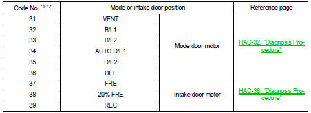
(If two or more mode or intake door motors malfunction, corresponding code Nos. indicates 1 second each.) *1: If mode door motor harness connector is disconnected, the following display pattern will appear.
31→32→33→34→35→36 Return to 31
*2: If intake door motor harness connector is disconnected, the following display pattern will appear.
37→38→39→Return to 37
>> Inspection End
Auxiliary Mechanism Trimmers
Refer to HAC-6, "Auxiliary Mechanism Trimmers".
 Diagnosis system (ECM)
 Component diagnosis