Nissan Altima (L32) 2007-2012 Service Manual: Steering gear and linkage
Exploded View
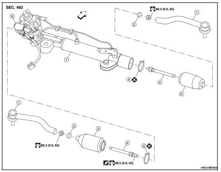
1. Outer socket
2. Boot clamp
3. Boot
4. Inner socket
5. Boot clamp
6. SSPS valve (part of gear assembly)
7. Gear assembly


Disassembly
1. Remove outer socket locknut and outer socket 2. Remove boot clamps and boot.
3. Remove inner socket.
Inspection
INSPECTION AFTER DISASSEMBLY
Boot
Check boot for cracks. Replace if there are.
Outer Socket and Inner Socket
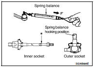
1. Ball joint swinging torque
• Hook a tool at the point shown in the figure and pull the spring balance. Make sure that the spring balance reads the specified value when ball stud and inner socket start to move.
Replace outer socket and steering gear assembly if they are outside the standard.
Tool number : — (J-44372)
2. Ball joint rotating torque
• Make sure that the reading is within the following specified range using Tool. Replace outer socket if the reading is outside the specified value.
Tool number : ST31227S000 (J-25765-A)
3. Ball joint axial end play
• Apply an axial load of 490 N (50 kg-f, 111 lb-f) to ball stud using a dial gauge. Measure amount of stud movement, and then make sure that the value is within the following specified range. Replace outer socket and inner socket if the measured value is outside the standard.
Assembly
1. Apply Three Bound TB1111 or equivalent to inner socket and turn pinion fully to left with inner socket installed to gear housing assembly.
2. Install large end of boot to gear housing assembly.
3. Install small end of boot to inner socket boot mounting groove.
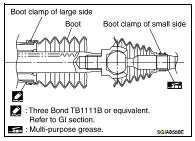
4. Install boot clamp to boot small end.
5. Install boot clamp to boot large end.
6. Adjust inner socket to standard length “L”, and then tighten lock nut to the specified torque. Refer to ST-28, "Exploded View".
Check length of inner socket “L” again after tightening lock nut.
Make sure that the length is the standard.

CAUTION: Adjust toe-in after this procedure. Length achieved after toe-in adjustment should not be more than 98.3 mm max.
 Steering column
 Power steering oil pump