Nissan Altima (L32) 2007-2012 Service Manual: Steering switch (sedan)
Description
When one of the steering wheel audio control switches is pushed, the resistance in steering switch circuit changes depending on which button is pushed.
Diagnosis Procedure
WITH BLUETOOTH
1.CHECK HARNESS
1. Turn ignition switch OFF.
2. Disconnect Bluetooth control unit connector B126 and spiral cable connector M30.
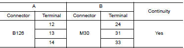
3. Check continuity between Bluetooth control unit connector B126 (A) terminals and spiral cable connector M30 (B) terminals.
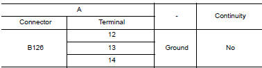
4. Check continuity between Bluetooth control unit B126 (A) and ground.
Are the continuity test results as specified? YES >> GO TO 2
NO >> Repair harness.
2.CHECK HARNESS
1. Disconnect audio unit connector.
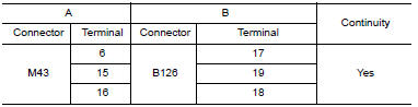
2. Check continuity between audio unit connector M43 (A) terminals and Bluetooth control unit connector B126 (B) terminals.
Are the continuity test results as specified? YES >> GO TO 3
NO >> Repair harness.
3.SPIRAL CABLE CHECK
1. Disconnect spiral cable connector M88.
2. Check continuity between spiral cable harness connector M30 and M88.
Are the continuity test results as specified? YES >> GO TO 4
NO >> Replace spiral cable. Refer to SR-8, "Removal and Installation".
4.CHECK STEERING SWITCH
Check steering switch. Refer to AV-146, "Component Inspection".
Does the steering switch pass inspection? YES >> Replace Bluetooth control unit. Refer to AV-235, "Removal and Installation - Sedan" NO >> Replace steering switch. Refer to AV-225, "Removal and Installation".
WITHOUT BLUETOOTH
1.CHECK STEERING SWITCH
Check steering switch. Refer to AV-146, "Component Inspection".
Does the steering switch pass inspection? YES >> GO TO 2
NO >> Replace steering switch. Refer to AV-225, "Removal and Installation".
2.CHECK HARNESS
1. Turn ignition switch OFF.
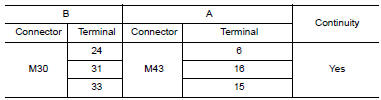
2. Disconnect audio unit connector M43 and spiral cable connector M30.
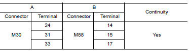
3. Check continuity between spiral cable harness connector M30 (B) and audio unit harness connector M43 (A).
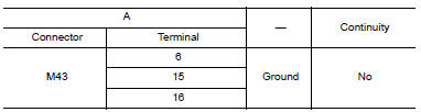
4. Check continuity between audio unit connector M43 (A) and ground.
Are the continuity test results as specified? YES >> GO TO 3
NO >> Repair harness.
3.SPIRAL CABLE CHECK
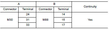
1. Disconnect spiral cable connector M88.
2. Check continuity between spiral cable harness connector M30 and M88.
Are the continuity test results as specified? YES >> Inspection End.
NO >> Replace spiral cable. Refer to SR-8, "Removal and Installation".
Component Inspection
WITH BLUETOOTH
Measure the resistance between the steering switch connector terminals 14 to 17 and 15 to 17.
Standard

WITHOUT BLUETOOTH
Measure the resistance between the steering switch connector terminals 14 to 17 and 15 to 17.
Standard
 Steering switch (coupe)
 Communication signal circuit
(coupe)
Communication signal circuit
(coupe)