Nissan Altima (L32) 2007-2012 Service Manual: Sunroof system
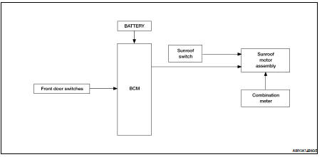
System Diagram
SUNROOF
System Description
SUNROOF SYSTEM
INPUT/OUTPUT SIGNAL CHART
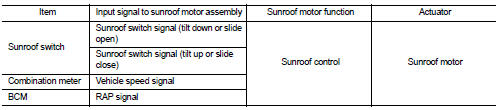
SUNROOF OPERATION
• Sunroof motor assembly operates with the power supply that is output from BCM while ignition switch is ON or retained power is operating.
• Tilt up/ down & slide open/ close signals from sunroof switch enables operate sunroof motor to move arbitrarily.
• Sunroof motor assembly receives a vehicle speed signal from combination meter and controls the sunroof motor torque of tilt-down at the time of high speed operation.
AUTO OPERATION
Sunroof AUTO feature makes it possible to slide open and slide close or tilt up and tilt down the sunroof without holding the sunroof switch in the slide open/tilt down or slide close/tilt up position.
RETAINED POWER OPERATION
• Retained power operation is an additional power supply function that enables sunroof system to operate during the 45 seconds even when ignition switch is turned OFF.
Retained power function cancel conditions
• Front door CLOSE (door switch OFF)→OPEN (door switch ON).
• When ignition switch is ON again.
• When timer time passes. (45 seconds)
ANTI-PINCH FUNCTION
The CPU of sunroof motor assembly monitors the sunroof motor operation and the sunroof position (fullyclosed or other) by the signals from sunroof motor.
When sunroof motor detects an interruption during the following slide close and tilt down operation, sunroof switch controls the motor for open and the sunroof will operate until full up position (when tilt down operate) or 150 mm (5.91 in) or more in an open direction (when slide close operate): • close operation and tilt down when ignition switch is in the “ON” position
Component Parts Location
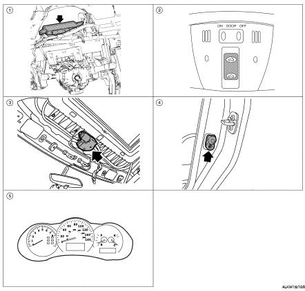
1. BCM M16, M17, M18 (View with instrument panel removed)
2. Sunroof switch R6
3. Sunroof motor assembly R5
4. Front door switch LH B8, RH B108
5. Combination meter M24
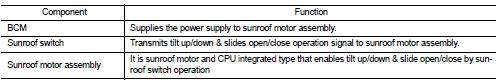
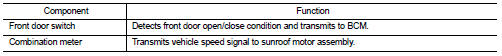
Component Description
 Function diagnosis
 Diagnosis system (BCM)