Nissan Altima (L32) 2007-2012 Service Manual: Trouble diagnosis - specification value
Description
The specification (SP) value indicates the tolerance of the value that is displayed in “SPEC” of “DATA MONITOR” mode of CONSULT-III during normal operation of the Engine Control System. When the value in “SPEC” in “DATA MONITOR” mode is within the SP value, the Engine Control System is confirmed OK. When the value in “SPEC” in “DATA MONITOR” mode is NOT within the SP value, the Engine Control System may have one or more malfunctions.
The SP value is used to detect malfunctions that may affect the Engine Control System, but will not illuminate the MIL.
The SP value will be displayed for the following three items: • B/FUEL SCHDL (The fuel injection pulse width programmed into ECM prior to any learned on board correction) • A/F ALPHA-B1/B2 (The mean value of air-fuel ratio feedback correction factor per cycle) • MAS A/F SE-B1 (The signal voltage of the mass air flow sensor)
Component Function Check
1.START
Check that all of the following conditions are satisfied.
• Vehicle driven distance: More than 5,000 km (3,107 miles) • Barometric pressure: 98.3 - 104.3 kPa (1.003 - 1.064 kg/cm2, 14.25 - 15.12 psi) • Atmospheric temperature: 20 - 30°C (68 - 86°F) • Engine coolant temperature: 75 - 95°C (167 - 203°F) • Transmission: Warmed-up
- CVT models: After the engine is warmed up to normal operating temperature, drive vehicle until “ATF TEMP SEN” in “DATA MONITOR” mode of “CVT” system indicates less than 0.9 V.
- M/T models: After the engine is warmed up to normal operating temperature, drive vehicle for 5 minutes.
• Electrical load: Not applied
- Rear window defogger switch, air conditioner switch lighting switch are OFF. Steering wheel is straight ahead.
• Engine speed: Idle
>> GO TO 2.
2.PERFORM “SPEC” OF “DATA MONITOR” MODE
NOTE: Perform “SPEC” in “DATA MONITOR” mode in maximum scale display.
1. Perform “EC-1048, "BASIC INSPECTION : Special Repair Requirement".
2. Select “B/FUEL SCHDL”, “A/F ALPHA-B1”, “A/F ALPHA-B2” and “MAS A/F SE-B1” in “SPEC” of “DATA MONITOR” mode with CONSULT-III.
3. Check that monitor items are within the SP value.
Is the measurement value within the SP value? YES >> INSPECTION END
NO >> Go to EC-1168, "Diagnosis Procedure".
Diagnosis Procedure
OVERALL SEQUENCE
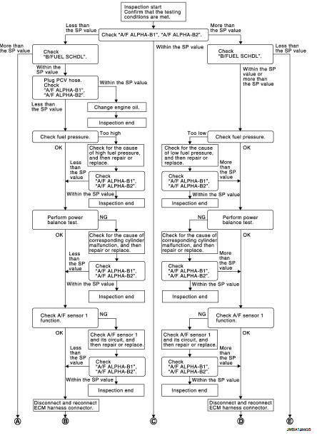
DETAILED PROCEDURE
1.CHECK “A/F ALPHA-B1”, “A/F ALPHA-B2”

1. Start engine.
2. Confirm that the testing conditions are met. Refer to EC-1167, "Component Function Check".
3. Select “A/F ALPHA-B1”, “A/F ALPHA-B2” in “SPEC” of “DATA MONITOR” mode, and check that each indication is within the SP value.
NOTE: Check “A/F ALPHA-B1”, “A/F ALPHA-B2” for approximately 1 minute because they may fluctuate. It is NG if the indication is out of the SP value even a little.
Is the measurement value within the SP value? YES >> GO TO 17.
NO-1 >> Less than the SP value: GO TO 2.
NO-2 >> More than the SP value: GO TO 3.
2.CHECK “B/FUEL SCHDL”
Select “B/FUEL SCHDL” in “SPEC” of “DATA MONITOR” mode, and check that the indication is within the SP value.
Is the measurement value within the SP value? YES >> GO TO 4.
NO >> More than the SP value: GO TO 19.
3.CHECK “B/FUEL SCHDL”
Select “B/FUEL SCHDL” in “SPEC” of “DATA MONITOR” mode, and check that the indication is within the SP value.
Is the measurement value within the SP value? YES >> GO TO 6.
NO-1 >> More than the SP value: GO TO 6.
NO-2 >> Less than the SP value: GO TO 25.
4.CHECK “A/F ALPHA-B1”, “A/F ALPHA-B2”
1. Stop the engine.
2. Disconnect PCV hose, and then plug it.
3. Start engine.
4. Select “A/F ALPHA-B1”, “A/F ALPHA-B2” in “SPEC” of “DATA MONITOR” mode, and check that each indication is within the SP value.
Is the measurement value within the SP value? YES >> GO TO 5.
NO >> GO TO 6.
5.CHANGE ENGINE OIL
1. Stop the engine.
2. Change engine oil.
NOTE: This symptom may occur when a large amount of gasoline is mixed with engine oil because of driving conditions (such as when engine oil temperature does not rise enough since a journey distance is too short during winter). The symptom will not be detected after changing engine oil or changing driving conditions.
>> INSPECTION END
6.CHECK FUEL PRESSURE
Check fuel pressure. (Refer to EC-1579, "Inspection".) Is the inspection result normal? YES >> GO TO 9.
NO-1 >> Fuel pressure is too high: Replace “fuel filter and fuel pump assembly” and then. GO TO 8.
NO-2 >> Fuel pressure is too low: GO TO 7.
7.DETECT MALFUNCTIONING PART
Check fuel hoses and fuel tubes for clogging.
Is the inspection result normal? YES >> Replace “fuel filter and fuel pump assembly” and then GO TO 8.
NO >> Repair or replace malfunctioning part and then GO TO 8.
8.CHECK “A/F ALPHA-B1”, “A/F ALPHA-B2”
1. Start engine.
2. Select “A/F ALPHA-B1”, “A/F ALPHA-B2” in “SPEC” of “DATA MONITOR” mode, and check that each indication is within the SP value.
Is the measurement value within the SP value? YES >> INSPECTION END
NO >> GO TO 9.
9.PERFORM POWER BALANCE TEST
1. Perform “POWER BALANCE” in “ACTIVE TEST” mode.
2. Check that each cylinder produces a momentary engine speed drop.
Is the inspection result normal? YES >> GO TO 12.
NO >> GO TO 10.
10.DETECT MALFUNCTIONING PART
Check the following below.
• Ignition coil and its circuit (Refer to EC-1491, "Component Function Check".) • Fuel injector and its circuit (Refer to EC-1483, "Component Function Check".) • Intake air leakage • Low compression pressure (Refer to EM-128, "On-Vehicle Service".) Is the inspection result normal? YES >> Replace fuel injector and then GO TO 11.
NO >> Repair or replace malfunctioning part and then GO TO 11.
11.CHECK “A/F ALPHA-B1”, “A/F ALPHA-B2”
1. Start engine.
2. Select “A/F ALPHA-B1”, “A/F ALPHA-B2” in “SPEC” of “DATA MONITOR” mode, and check that each indication is within the SP value.
Is the measurement value within the SP value? YES >> INSPECTION END
NO >> GO TO 12.
12.CHECK A/F SENSOR 1 FUNCTION
Perform all DTC CONFIRMATION PROCEDURE related with A/F sensor 1.
• For DTC P0130, P0150, refer to EC-1225, "DTC Logic".
• For DTC P0131, P0151, refer to EC-1229, "DTC Logic".
• For DTC P0132, P0152, refer to EC-1233, "DTC Logic".
• For DTC P0133, P0153, refer to EC-1237, "DTC Logic".
• For DTC P2A00, P2A03, refer to EC-1463, "DTC Logic".
Are any DTCs detected? YES >> GO TO 15.
NO >> GO TO 13.
13.CHECK A/F SENSOR 1 CIRCUIT
Perform Diagnostic Procedure according to corresponding DTC.
>> GO TO 14.
14.CHECK “A/F ALPHA-B1”, “A/F ALPHA-B2”
1. Start engine.
2. Select “A/F ALPHA-B1”, “A/F ALPHA-B2” in “SPEC” of “DATA MONITOR” mode, and check that each indication is within the SP value.
Is the measurement value within the SP value? YES >> INSPECTION END
NO >> GO TO 15.
15.DISCONNECT AND RECONNECT ECM HARNESS CONNECTOR
1. Stop the engine.
2. Disconnect ECM harness connector. Check pin terminal and connector for damage, and then reconnect it.
>> GO TO 16.
16.CHECK “A/F ALPHA-B1”, “A/F ALPHA-B2”
1. Start engine.
2. Select “A/F ALPHA-B1”, “A/F ALPHA-B2” in “SPEC” of “DATA MONITOR” mode, and check that each indication is within the SP value.
Is the measurement value within the SP value? YES >> INSPECTION END
NO >> Detect malfunctioning part according to EC-1567, "Symptom Table".
17.CHECK “B/FUEL SCHDL”
Select “B/FUEL SCHDL” in “SPEC” of “DATA MONITOR” mode, and check that the indication is within the SP value.
Is the measurement value within the SP value? YES >> INSPECTION END
NO-1 >> More than the SP value: GO TO 18.
NO-2 >> Less than the SP value: GO TO 25.
18.DETECT MALFUNCTIONING PART
1. Check for the cause of large engine friction. Refer to the following.
- Engine oil level is too high
- Engine oil viscosity
- Belt tension of power steering, alternator, A/C compressor, etc. is excessive
- Noise from engine
- Noise from transmission, etc.
2. Check for the cause of insufficient combustion. Refer to the following.
- Valve clearance malfunction
- Intake valve timing control function malfunction
- Camshaft sprocket installation malfunction, etc.
>> Repair or replace malfunctioning part, and then GO TO 30.
19.CHECK INTAKE SYSTEM
Check for the cause of uneven air flow via the mass air flow sensor. Refer to the following.
• Crushed air ducts
• Malfunctioning seal of air cleaner element
• Uneven dirt of air cleaner element
• Improper specification of intake air system
Is the inspection result normal? YES >> GO TO 21.
NO >> Repair or replace malfunctioning part, and then GO TO 20.
20.CHECK “A/F ALPHA-B1”, “A/F ALPHA-B2”, AND “B/FUEL SCHDL”
Select “A/F ALPHA-B1”, “A/F ALPHA-B2”, and “B/FUEL SCHDL” in “SPEC” of “DATA MONITOR” mode, and check that each indication is within the SP value.
Is the measurement value within the SP value? YES >> INSPECTION END
NO >> “B/FUEL SCHDL” is more, “A/F ALPHA-B1”, “A/F ALPHA-B2” are less than the SP value: GO TO 21.
21.DISCONNECT AND RECONNECT MASS AIR FLOW SENSOR HARNESS CONNECTOR
1. Stop the engine.
2. Disconnect mass air flow sensor harness connector. Check pin terminal and connector for damage and then reconnect it again.
>> GO TO 22.
22.CHECK “A/F ALPHA-B1”, “A/F ALPHA-B2”
1. Start engine.
2. Select “A/F ALPHA-B1”, “A/F ALPHA-B2” in “SPEC” of “DATA MONITOR” mode, and check that each indication is within the SP value.
Is the measurement value within the SP value? YES >> Detect malfunctioning part of mass air flow sensor circuit and repair it. Refer to EC-1202, "Diagnosis Procedure". Then GO TO 29.
NO >> GO TO 23.
23.CHECK “MAS A/F SE-B1”
Select “MAS A/F SE-B1” in “SPEC” of “DATA MONITOR” mode, and check that the indication is within the SP value.
Is the measurement value within the SP value? YES >> GO TO 24.
NO >> More than the SP value: Replace mass air flow sensor, and then GO TO 29.
24.REPLACE ECM
1. Replace ECM.
2. Refer to EC-1051, "ADDITIONAL SERVICE WHEN REPLACING CONTROL UNIT : Special Repair Requirement".
>> GO TO 29.
25.CHECK INTAKE SYSTEM
Check for the cause of uneven air flow via the mass air flow sensor. Refer to the following.
• Crushed air ducts
• Malfunctioning seal in air cleaner element
• Uneven dirt in air cleaner element
• Improper specification in intake air system
Is the inspection result normal? YES >> GO TO 27.
NO >> Repair or replace malfunctioning part, and then GO TO 26.
26.CHECK “B/FUEL SCHDL”
Select “B/FUEL SCHDL” in “SPEC” of “DATA MONITOR” mode, and check that the indication is within the SP value.
Is the measurement value within the SP value? YES >> INSPECTION END
NO >> Less than the SP value: GO TO 27.
27.CHECK “MAS A/F SE-B1”
Select “MAS A/F SE-B1” in “SPEC” of “DATA MONITOR” mode, and check that the indication is within the SP value.
Is the measurement value within the SP value? YES >> GO TO 28.
NO >> Less than the SP value: Replace mass air flow sensor, and then GO TO 30.
28.CHECK INTAKE SYSTEM
Check for the cause of air leakage after the mass air flow sensor. Refer to the following.
• Disconnection, looseness, and cracks in air duct
• Looseness of oil filler cap
• Disconnection of oil level gauge
• Open stuck, breakage, hose disconnection, or cracks in PCV valve
• Disconnection or cracks in EVAP purge hose, stuck open EVAP canister purge volume control solenoid valve
• Malfunctioning seal in rocker cover gasket
• Disconnection, looseness, or cracks in hoses, such as a vacuum hose, connecting to intake air system parts
• Malfunctioning seal in intake air system, etc.
>> GO TO 30.
29.CHECK “A/F ALPHA-B1”, “A/F ALPHA-B2”, AND “B/FUEL SCHDL”
Select “A/F ALPHA-B1”, “A/F ALPHA-B2”, and “B/FUEL SCHDL” in “SPEC” of “DATA MONITOR” mode, and check that each indication is within the SP value.
Is the measurement value within the SP value? YES >> INSPECTION END
NO >> Detect malfunctioning part according to EC-1567, "Symptom Table".
30.CHECK “B/FUEL SCHDL”
Select “B/FUEL SCHDL” in “SPEC” of “DATA MONITOR” mode, and then check that the indication is within the SP value.
Is the measurement value within the SP value? YES >> INSPECTION END
NO >> Detect malfunctioning part according to EC-1567, "Symptom Table".
 Component diagnosis
 Power supply and ground circuit