Nissan Altima (L32) 2007-2012 Service Manual: U1010 control unit (CAN)
Description
CAN (Controller Area Network) is a serial communication line for real time application. It is an on-vehicle multiplex communication line with high data communication speed and excellent malfunction detection ability.
Many electronic control units are equipped onto a vehicle, and each control unit shares information and links with other control units during operation (not independent). In CAN communication, control units are connected with 2 communication lines (CAN-H and CAN-L) allowing a high rate of information transmission with less wiring. Each control unit transmits/receives data but selectively reads required data only.
DTC Logic
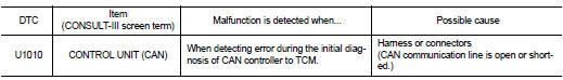
DTC DETECTION LOGIC
DTC CONFIRMATION PROCEDURE
NOTE: If “DTC CONFIRMATION PROCEDURE” has been previously performed, always turn ignition switch OFF.
Then wait at least 10 seconds before performing the next test.
1.CHECK DTC DETECTION

1. Turn ignition switch ON.
2. Start engine and wait for at least 6 seconds.
3. Perform “SELF-DIAG RESULTS” mode for “TRANSMISSION”.

Follow the procedure “With CONSULT-III”.
Is “U1010 CONTROL UNIT (CAN)” detected? YES >> Go to TM-303, "Diagnosis Procedure".
NO >> Check intermittent incident. Refer to GI-42, "Intermittent Incident".
Diagnosis Procedure
1.CHECK CAN COMMUNICATION CIRCUIT

1. Turn ignition switch ON and start engine.
2. Perform “SELF-DIAG RESULTS” mode for “TRANSMISSION”.
Is “U1010 CONTROL UNIT (CAN)” indicated? YES >> Go to LAN section. Refer to LAN-25, "CAN System Specification Chart".
NO >> Check intermittent incident. Refer to GI-42, "Intermittent Incident".
 U1000 can comm circuit
 P0703 stop lamp switch