Nissan Altima (L32) 2007-2012 Service Manual: Variable induction air system
Description
Power Valves 1 and 2
The power valves 1 and 2 are installed in intake manifold collector and used to control the suction passage of the variable induction air control system. They are set in the fully closed or fully opened position by the power valve actuators 1 and 2 operated by the vacuum stored in the vacuum tank. The vacuum to power valve actuators is controlled by the VIAS control solenoid valves 1 and 2.
Component Function Check
1.CHECK OVERALL FUNCTION-I

1. Start engine and warm it up to the normal operating temperature.
2. Perform “VIAS S/V-1” in “ACTIVE TEST” mode with CONSULT-III.
3. Turn VIAS control solenoid valve 1 ON and OFF, and check that power valve actuator 1 rod moves.

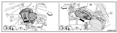
1. Power valve actuator 1
2. Power valve actuator 1 rod
3. Power valve actuator 2
4. Power valve actuator 2 rod


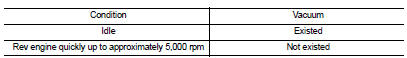
1. Start engine and warm it up to the normal operating temperature.
2. Rev engine quickly up to approximately 5,000 rpm.
3. Check that power valve actuator 1 rod moves.
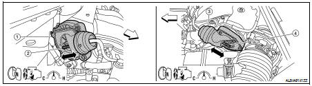
1. Power valve actuator 1
2. Power valve actuator 1 rod
3. Power valve actuator 2
4. Power valve actuator 2 rod

Is the inspection result normal? YES >> GO TO 2.
NO >> EC-1507, "Diagnosis Procedure".
2.CHECK OVERALL FUNCTION-II

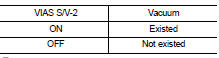
1. Perform “VIAS S/V-2” in “ACTIVE TEST” mode with CONSULT-III.
2. Turn VIAS control solenoid valve 2 ON and OFF, and check that power valve actuator 2 rod moves.
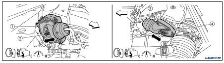
1. Power valve actuator 1
2. Power valve actuator 1 rod
3. Power valve actuator 2
4. Power valve actuator 2 rod


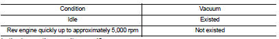
1. When revving engine up to 5,000 rpm quickly.
2. Rev engine quickly up to approximately 5,000 rpm.
3. Check that power valve actuator 2 rod moves.
1. Power valve actuator 1
2. Power valve actuator 1 rod
3. Power valve actuator 2
4. Power valve actuator 2 rod

Is the inspection result normal? YES >> INSPECTION END
NO >> EC-1507, "Diagnosis Procedure".
Diagnosis Procedure
1.INSPECTION START
Confirm the malfunctioning system (power valve 1 or power valve 2). Refer to EC-1506, "Component Function Check".
Which system is related to the incident? Power valve 1>>GO TO 2.
Power valve 2>>GO TO 6.
2.CHECK VACUUM EXISTENCE-I

1. Stop engine and disconnect vacuum hose connected to power valve actuator 1.
2. Start engine and let it idle.
3. Perform “VIAS S/V-1” in “ACTIVE TEST” mode with CONSULT-III.
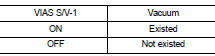
4. Turn VIAS control solenoid valve 1 ON and OFF, and check vacuum existence under the following conditions.

1. Stop engine and disconnect vacuum hose connected to power valve actuator 1.
2. Disconnect VIAS control solenoid valve 1 harness connector.
3. Start engine.
4. Rev engine quickly up to approximately 5,000 rpm.
5. Check vacuum existence under the following conditions.
Is the inspection result normal? YES >> Repair or replace power valve actuator 1.
NO >> GO TO 3.
3.CHECK VACUUM TANK
1. Stop engine and disconnect vacuum hose connected to intake manifold collector.
2. Start engine and let it idle.
3. Check vacuum existence from intake manifold collector.
Does vacuum existence from the intake manifold collector? YES >> GO TO 4.
NO >> Replace intake manifold collector.
4.CHECK VACUUM HOSE
1. Stop engine.
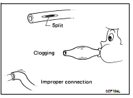
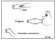
2. Check vacuum hose for cracks, clogging, improper connection or disconnection. Refer to EC-1133, "System Diagram".
Is the inspection result normal? YES >> GO TO 5.
NO >> Repair hoses or tubes.
5.CHECK VIAS CONTROL SOLENOID VALVE 1
Refer to EC-1429, "Component Inspection".
Is the inspection result normal? YES >> GO TO 9.
NO >> Replace VIAS control solenoid valve 1.
6.CHECK VACUUM EXISTENCE-II

1. Stop engine and disconnect vacuum hose connected to power valve actuator 2.
2. Start engine and let it idle.
3. Perform “VIAS S/V-2” in “ACTIVE TEST” mode with CONSULT-III.
4. Turn VIAS control solenoid valve 2 ON and OFF, and check vacuum existence under the following conditions.

1. Stop engine and disconnect vacuum hose connected to power valve actuator 2.
2. Disconnect VIAS control solenoid valve 1 harness connector.
3. Start engine.
4. Rev engine quickly up to approximately 5,000 rpm.
5. Check vacuum existence under the following conditions.
Is the inspection result normal? YES >> Repair or replace power valve actuator 2.
NO >> GO TO 7.
7.CHECK VACUUM HOSE
1. Stop engine.
2. Check vacuum hose for cracks, clogging, improper connection or disconnection. Refer to EC-1133, "System Diagram".
Is the inspection result normal? YES >> GO TO 8.
NO >> Repair hoses or tubes.
8.CHECK VIAS CONTROL SOLENOID VALVE 2
Refer to EC-1432, "Component Inspection".
Is the inspection result normal? YES >> GO TO 9.
NO >> Replace VIAS control solenoid valve 2.
9.CHECK INTERMITTENT INCIDENT
Refer to GI-42, "Intermittent Incident".
>> INSPECTION END
 Refrigerant pressure sensor
 ECU Diagnosis