Nissan Altima (L32) 2007-2012 Service Manual: Air pressure monitor
Diagnosis Description
DESCRIPTION
During driving, the TPMS receives the signal transmitted from the transmitter installed in each wheel, when the tire pressure becomes low. The control unit (BCM) of this system has pressure judgment and trouble diagnosis functions.
When the TPMS detects low inflation pressure or another unusual symptom, the warning lamps in the combination meter comes on.
SELF DIAGNOSTIC PROCEDURE (WITH CONSULT-III)

• Touch “SELF-DIAG RESULTS” display shows malfunction experienced since the last erasing operation.
Refer to BCS-91, "DTC Index".
SELF DIAGNOSTIC PROCEDURE (WITHOUT CONSULT-III)

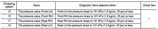
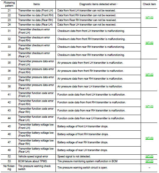
To start the self-diagnostic results mode, ground terminal of the tire pressure warning check connector. The malfunction location is indicated by the warning lamp flashing.
NOTE: When the low tire warning lamp flashes 5 Hz and continues repeating it, the system is normal.
ERASE SELF-DIAGNOSIS

1. Perform applicable inspection of malfunctioning item and then repair or replace.
2. Turn ignition switch “ON” and select “SELF-DIAG RESULTS” mode for “AIR PRESSURE MONITOR” with CONSULT-III.
3. Touch “ERASE” on CONSULT-III screen to erase memory.

• In order to make it easier to find the cause of hard-to-duplicate malfunctions, malfunction information is stored into the control unit as necessary during use by the user. This memory is not erased no matter how many times the ignition switch is turned “ON” and“OFF”.
• However, this information is erased by turning ignition switch “OFF” after performing self-diagnostic or by erasing the memory using the CONSULT-III.
CONSULT-III Function (BCM-AIR PRESSURE MONITOR)
WORK SUPPORT
ID Read
The registered ID number is displayed.
ID Regist
Refer to WT-6.
SELF-DIAG RESULTS
Operation Procedure
Refer to BCS-91, "DTC Index".
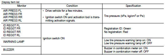
DATA MONITOR
Screen of data monitor mode is displayed.
NOTE: When malfunction is detected, CONSULT-III perform REAL-TIME DIAGNOSIS.
Also, any malfunction detected while in this mode will be displayed at real time.
NOTE: Before performing the self-diagnosis, be sure to register the ID, or erase the actual malfunction location may be different from that displayed on CONSULT-III.
ACTIVE TEST
TEST ITEM LIST
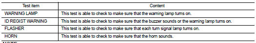
NOTE: Before performing the self-diagnosis, be sure to register the ID, or else the actual malfunction may be different from that displayed on CONSULT-III.
 Signal buffer
 Component diagnosis