Nissan Altima (L32) 2007-2012 Service Manual: ASCD brake switch
Description
When the brake pedal is depressed, ASCD brake switch is turned OFF and stop lamp switch is turned ON.
ECM detects the state of the brake pedal by this input of two kinds (ON/OFF signal).
Refer to EC-67, "System Description" for the ASCD function.
Component Function Check
1.CHECK FOR ASCD BRAKE SWITCH FUNCTION

1. Turn ignition switch ON.
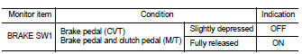
2. Select “BRAKE SW1” in “DATA MONITOR” mode with CONSULT-III.
3. Check “BRAKE SW1” indication under the following conditions.

1. Turn ignition switch ON.
2. Check the voltage between ECM harness connector and ground.
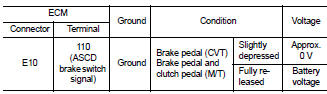
Is the inspection result normal? YES >> INSPECTION END.
NO >> Refer to EC-450, "Diagnosis Procedure".
Diagnosis Procedure
1.CHECK OVERALL FUNCTION-I
Check which type of transmission the vehicle is equipped with.
Is the inspection result normal? CVT >> GO TO 2.
M/T >> GO TO 6.
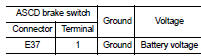
2.CHECK ASCD BRAKE SWITCH POWER SUPPLY CIRCUIT
1. Turn ignition switch OFF.
2. Disconnect ASCD brake switch harness connector.
3. Turn ignition switch ON.
4. Check the voltage between ASCD brake switch harness connector and ground.
Is the inspection result normal? YES >> GO TO 4.
NO >> GO TO 3.
3.DETECT MALFUNCTIONING PART
Check the following.
• Fuse block (J/B) connector E6
• Junction block connector E44, E46
• 10A fuse (No. 3) • Harness for open or short between ASCD brake switch and fuse
>> Repair open circuit or short to ground or short to power in harness or connectors.
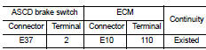
4.CHECK ASCD BRAKE SWITCH INPUT SIGNAL CIRCUIT FOR OPEN AND SHORT
1. Turn ignition switch OFF.
2. Disconnect ECM harness connector.
3. Check the continuity between ASCD brake switch harness connector and ECM harness connector.
4. Also check harness for short to ground and short to power.
Is the inspection result normal? YES >> GO TO 5.
NO >> Repair open circuit or short to ground or short to power in harness or connectors.
5.CHECK ASCD BRAKE SWITCH
Refer to EC-453, "Component Inspection (ASCD Brake Switch)".
Is the inspection result normal? YES >> GO TO 13.
NO >> Replace ASCD brake switch.
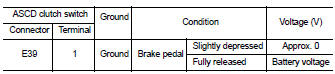
6.CHECK ASCD BRAKE SWITCH CIRCUIT
1. Turn ignition switch OFF.
2. Disconnect ASCD clutch switch harness connector.
3. Turn ignition switch ON.
4. Check the continuity between ASCD clutch switch harness connector and ground.
5. Also check harness for short to ground and short to power.
Is the inspection result normal? YES >> GO TO 11.
NO >> GO TO 7.
7.CHECK ASCD BRAKE SWITCH POWER SUPPLY CIRCUIT
1. Turn ignition switch OFF.
2. Disconnect ASCD brake switch harness connector.
3. Turn ignition switch ON.
4. Check the voltage between ASCD brake switch harness connector and ground.
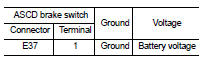
Is the inspection result normal? YES >> GO TO 9.
NO >> GO TO 8.
8.DETECT MALFUNCTIONING PART
Check the following.
• Fuse block (J/B) connector E6
• Junction block connector E44, E46
• 10A fuse (No. 3) • Harness for open or short between ASCD brake switch and fuse
>> Repair open circuit or short to ground or short to power in harness or connectors.
9.CHECK ASCD BRAKE SWITCH INPUT SIGNAL CIRCUIT FOR OPEN AND SHORT
1. Turn ignition switch OFF.
2. Check the continuity between ASCD brake switch harness connector and ASCD clutch switch harness connector.
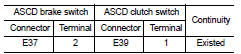
3. Also check harness for short to ground and short to power.
Is the inspection result normal? YES >> GO TO 10.
NO >> Repair open circuit or short to ground or short to power in harness or connectors.
10.CHECK ASCD BRAKE SWITCH
Refer to EC-453, "Component Inspection (ASCD Brake Switch)".
Is the inspection result normal? YES >> GO TO 13.
NO >> Replace ASCD brake switch.
11.CHECK ASCD BRAKE SWITCH INPUT SIGNAL CIRCUIT FOR OPEN AND SHORT
1. Turn ignition switch OFF.
2. Disconnect ECM harness connector
3. Check the continuity between ASCD clutch switch harness connector and ECM harness connector.
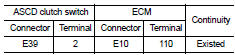
4. Also check harness for short to ground and short to power.
Is the inspection result normal? YES >> GO TO 12.
NO >> Repair open circuit or short to ground or short to power in harness or connectors.
12.CHECK ASCD CLUTCH SWITCH
Refer to EC-453, "Component Inspection (ASCD Clutch Switch)".
Is the inspection result normal? YES >> GO TO 13.
NO >> Replace ASCD clutch switch.
13.CHECK INTERMITTENT INCIDENT
Refer to GI-42, "Intermittent Incident".
>> INSPECTION END
Component Inspection (ASCD Brake Switch)
1.CHECK ASCD BRAKE SWITCH-I
1. Turn ignition switch OFF.
2. Disconnect ASCD brake switch harness connector.
3. Check the continuity between ASCD brake switch terminals under the following conditions.
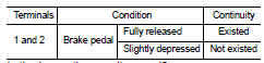
Is the inspection result normal? YES >> INSPECTION END
NO >> GO TO 2.
2.CHECK ASCD BRAKE SWITCH-II
1. Adjust ASCD brake switch installation. Refer to BR-13, "Inspection and Adjustment".
2. Check the continuity between ASCD brake switch terminals under the following conditions.
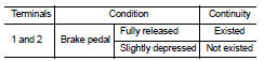
Is the inspection result normal? YES >> INSPECTION END
NO >> Replace ASCD brake switch.
Component Inspection (ASCD Clutch Switch)
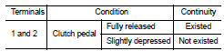
1.CHECK ASCD CLUTCH SWITCH-I
1. Turn ignition switch OFF.
2. Disconnect ASCD clutch switch harness connector.
3. Check the continuity between ASCD clutch switch terminals under the following conditions.
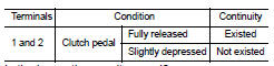
Is the inspection result normal? YES >> INSPECTION END
NO >> GO TO 2.
2.CHECK ASCD CLUTCH SWITCH-II
1. Adjust ASCD clutch switch installation. Refer to BR-13, "Inspection and Adjustment".
2. Check the continuity between ASCD clutch switch terminals under the following conditions.
Is the inspection result normal? YES >> INSPECTION END
NO >> Replace ASCD clutch switch.
 P2A00 A/F sensor 1
 ASCD indicator