Nissan Altima (L32) 2007-2012 Service Manual: Auto light system
System Diagram
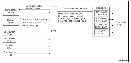
System Description
• BCM (Body Control Module) controls auto light operation according to signals from optical sensor, lighting switch and ignition switch.
• IPDM E/R (Intelligent Power Distribution Module Engine Room) operates parking, license plate, tail, front fog lamps and headlamps according to CAN communication signals from BCM.
• Optical sensor detects ambient brightness of 800 to 2,500 lux. And optical sensor converts light (lux) to voltage, then sends the optical sensor signal to BCM.
OUTLINE
The auto light control system has an optical sensor that detects outside brightness.
When the lighting switch is in AUTO position, it automatically turns ON/OFF the parking, license plate, tail, front fog lamps and headlamps in accordance with the ambient light. Sensitivity can be adjusted in four steps.
For the details of the setting, Refer to EXL-26, "COMMON ITEM : CONSULT-III Function".
Component Parts Location
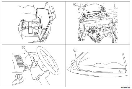
1. IPDM E/R E17, E18, E200
2. BCM M16, M17, M18, M19, M21 (view with instrument panel removed)
3. Combination switch M28
4. Optical sensor M66
Component Description
AUTO LIGHT OPERATION
Applicable lamps
• Low beam headlamp
• Parking, license plate and tail lamps
• High beam headlamp (with the lighting switch in HIGH BEAM position)
• Front fog lamp (with the lighting switch in front fog lamp ON position)
When the lighting switch is in AUTO position with the ignition switch in ON position, BCM detects the AUTO LIGHT (ON) by BCM combination switch reading function. BCM turns automatically ON/OFF the applicable lamps according to ambient brightness.
NOTE: Timing for when lamps turn ON/OFF can be changed by the function setting of CONSULT-III. Refer to EXL-26, "COMMON ITEM : CONSULT-III Function".
 Daytime running light system
 Front fog lamp