Nissan Altima (L32) 2007-2012 Service Manual: B2110 PNP/clutch interlock switch
Description
IPDM E/R confirms the shift position with the following signals.
• Park/neutral position (PNP) switch (CVT models) • Clutch inter lock switch (M/T models) • Shift position signal from BCM (CAN)
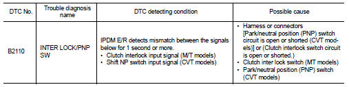
DTC Logic
DTC DETECTION LOGIC
NOTE: • If DTC B2110 is displayed with DTC U1000, first perform the trouble diagnosis for DTC U1000. Refer to SEC-36, "DTC Logic".
• If DTC B2110 is displayed with DTC U1010, first perform the trouble diagnosis for DTC U1010. Refer to SEC-37, "DTC Logic".
DTC CONFIRMATION PROCEDURE
1.PERFORM DTC CONFIRMATION PROCEDURE
1. Turn the ignition switch ON under the following conditions and wait for at least 1 second.
- CVT selector lever is in the P or N position
- Do not depress the brake pedal
2. Check “Self diagnostic result” with CONSULT-III.
Is DTC detected? YES >> Refer to SEC-59, "Diagnosis Procedure".
NO >> Inspection End.
Diagnosis Procedure
1.INSPECTION START
Check which type of transmission the vehicle is equipped with.
Which type of transmission CVT >> GO TO 2
M/T >> GO TO 5
2.CHECK DTC WITH BCM
Refer to BCS-91, "DTC Index".
Is the inspection result normal? YES >> GO TO 3
NO >> Repair or replace malfunctioning parts.
3.CHECK PNP SWITCH INPUT SIGNAL
1. Turn ignition switch OFF.
2. Disconnect IPDM E/R harness connector.
3. Turn ignition switch ON.
4. Check voltage between IPDM E/R harness connector and ground under following condition.
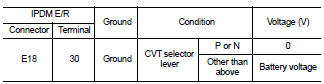
Is the inspection result normal? YES >> Replace IPDM E/R. Refer to PCS-48, "Removal and Installation".
NO >> (VQ35DE) GO TO 4
NO >> (QR25DE) GO TO 10
4.CHECK PNP SWITCH CIRCUIT
1. Turn ignition switch OFF.
2. Disconnect TCM harness connector.
3. Check continuity between IPDM E/R harness connector and TCM harness connector.
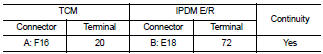
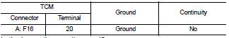
4. Check continuity between TCM harness connector and ground.
Is the inspection result normal? YES >> GO TO 13
NO >> Repair harness or connector.
5.CHECK CLUTCH INTERLOCK SWITCH INPUT SIGNAL (BCM)
1. Turn ignition switch OFF.
2. Disconnect BCM harness connector.
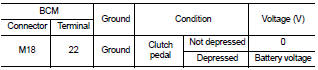
3. Check voltage between BCM harness connector and ground.
Is the inspection result normal? YES >> GO TO 6
NO >> GO TO 7
6.CHECK CLUTCH INTERLOCK SWITCH INPUT SIGNAL
1. Turn ignition switch OFF.
2. Disconnect IPDM E/R harness connector.
3. Turn ignition switch ON.
4. Check voltage between IPDM E/R harness connector and ground.
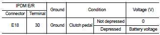
Is the inspection result normal? YES >> Replace the IPDM E/R. Refer to PCS-48, "Removal and Installation".
NO >> Check harness for open between clutch interlock switch and IPDM E/R.
7.CHECK CLUTCH INTERLOCK SWITCH POWER SUPPLY
1. Disconnect clutch interlock switch harness connector.
2. Check voltage between clutch interlock switch harness connector and ground.
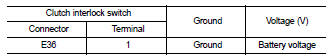
Is the inspection result normal? YES >> GO TO 8
NO >> Check harness for open or short between clutch interlock switch and fuse.
8.CHECK CLUTCH INTERLOCK SWITCH CIRCUIT
1. Check continuity between IPDM E/R harness connector and clutch interlock switch harness connector.
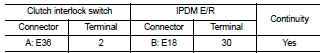
2. Check continuity between clutch interlock switch harness connector and ground.
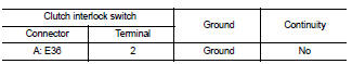
Is the inspection result normal? YES >> GO TO 9
NO >> Repair harness or connector.
9.CHECK CLUTCH INTERLOCK SWITCH
Refer to SEC-62, "Component Inspection".
Is the inspection result normal? YES >> Replace the IPDM E/R. Refer to PCS-48, "Removal and Installation".
NO >> Replace clutch interlock switch.
10.CHECK PNP SWITCH CIRCUIT FOR CONTINUITY
1. Turn ignition switch OFF.
2. Check continuity between IPDM E/R harness connector terminals 72 and 74.
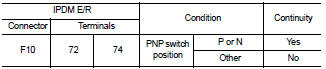
Is the inspection result normal? YES >> GO TO 11
NO >> GO TO 12
11.CHECK PNP SWITCH CIRCUIT FOR SHORT
Check continuity between IPDM E/R harness connector terminals 72, 74 and ground.
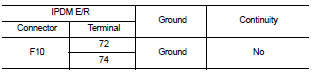
Is the inspection result normal? YES >> Replace the IPDM E/R. Refer to PCS-48, "Removal and Installation".
NO >> Repair or replace harness.
12.CHECK PNP SWITCH INPUT SIGNAL CIRCUIT
1. Disconnect PNP switch harness connector.
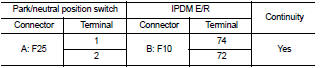
2. Check continuity between PNP switch and IPDM E/R harness connectors.
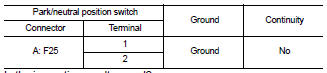
3. Check continuity between PNP switch harness connector and ground.
Is the inspection result normal? YES >> Replace PNP switch.
NO >> Repair harness or connector.
13.CHECK INTERMITTENT INCIDENT
Refer to GI-42, "Intermittent Incident".
>> Inspection End.
Component Inspection
1.CHECK CLUTCH INTERLOCK SWITCH
1. Turn ignition switch OFF.
2. Disconnect clutch interlock switch harness connector.
3. Check continuity between clutch interlock switch under the following conditions.
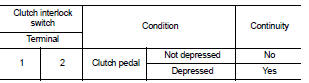
Is the inspection result normal? YES >> Inspection End.
NO >> Replace clutch interlock switch.
 B210F PNP/clutch interlock switch
 B2190, P1610 nats antenna AMP