Nissan Altima (L32) 2007-2012 Service Manual: B2190, P1610 nats antenna amp
Description
Performs ID verification through BCM and keyfob when push-button ignition switch is pressed.
Prohibits the release of steering lock or start of engine when an unregistered ID of keyfob is used.
DTC Logic
DTC DETECTION LOGIC
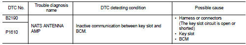
DTC CONFIRMATION PROCEDURE
1.PERFORM DTC CONFIRMATION PROCEDURE
1. Insert keyfob into the key slot.
2. Check “Self Diagnostic Result” with CONSULT-III.
Is DTC detected? YES >> Refer to SEC-455, "Diagnosis Procedure".
NO >> GO TO 2
2.PERFORM DTC CONFIRMATION PROCEDURE
1. Press the push-button ignition switch.
2. Check “Self Diagnostic Result” with CONSULT-III.
Is DTC detected? YES >> Refer to SEC-455, "Diagnosis Procedure".
NO >> Inspection End.
Diagnosis Procedure
1. INSPECTION START
Check the case in which DTC is detected.
• Case1: It is detected when keyfob is inserted into key slot.
• Case2: It is detected after keyfob is inserted into key slot and push-button ignition switch is pressed.
In which case is DTC detected? Case1. >> GO TO 2
Case2. >> GO TO 4
2.CHECK KEY SLOT INPUT SIGNAL
1. Turn ignition switch OFF.
2. Disconnect key slot harness connector.
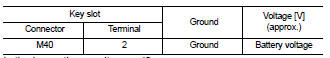
3. Check voltage between key slot harness connector and ground.
Is the inspection result normal? YES >> Replace key slot. Refer to SEC-596, "Removal and Installation".
NO >> GO TO 3
3.CHECK KEY SLOT CIRCUIT
1. Disconnect BCM harness connector.
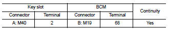
2. Check continuity between key slot harness connector M40 (A) terminal 2 and BCM harness connector M19 (B) terminal 68.
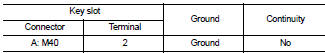
3. Check continuity between key slot harness connector M40 (A) terminal 2 and ground.
Is the inspection result normal? YES >> GO TO 8
NO >> Repair harness or connector.
4.CHECK PUSH-IGNITION SWITCH OPERATION
Press push-button ignition switch and check if it turns ON.
Does ignition switch turn to ON? YES >> GO TO 5
NO >> GO TO 7
5.CHECK KEY SLOT COMMUNICATION SIGNAL
1. Turn ignition switch OFF.
2. Disconnect key slot harness connector.
3. Check voltage between key slot harness connector and ground.
Is the inspection result normal? YES >> Replace key slot. Refer to SEC-596, "Removal and Installation".
NO >> GO TO 6
6.CHECK KEY SLOT COMMUNICATION SIGNAL CIRCUIT
1. Disconnect BCM harness connector.
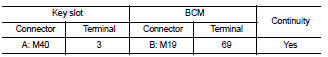
2. Check continuity between key slot harness connector M40 (A) terminal 3 and BCM harness connector M19 (B) terminal 69.
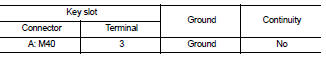
3. Check continuity between key slot harness connector M40 (A) terminal 3 and ground.
Is the inspection result normal? YES >> GO TO 8
NO >> Repair harness or connector.
7.CHECK KEY SLOT GROUND CIRCUIT
1. Turn ignition switch OFF.
2. Disconnect key slot harness connector.
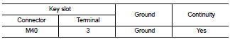
3. Check continuity between key slot harness connector and ground.
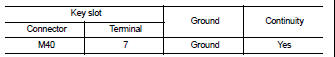
Is the inspection result normal? YES >> GO TO 8
NO >> Repair harness or connector.
8.CHECK INTERMITTENT INCIDENT
Refer to GI-42, "Intermittent Incident".
>> Inspection End.
 B2110 PNP/Clutch interlock switch
 B2191, P1615 Difference of key