Nissan Altima (L32) 2007-2012 Service Manual: B261a push-button ignition switch
Description
IPDM E/R transmits the push-button ignition switch status via CAN communication to BCM. BCM receives push-button ignition switch status by hardwire input. BCM compares the 2 signals for mismatch.
DTC Logic
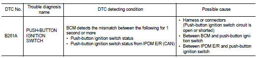
DTC DETECTION LOGIC
NOTE: • If DTC B261A is displayed with DTC U1000, first perform the trouble diagnosis for DTC U1000. Refer to SEC-36, "DTC Logic".
• If DTC B261A is displayed with DTC U1010, first perform the trouble diagnosis for DTC U1010. Refer to SEC-37, "DTC Logic".
DTC CONFIRMATION PROCEDURE
1.PERFORM DTC CONFIRMATION PROCEDURE
1. Press the push-button ignition switch under the following conditions and wait for at least 1 second.
- CVT selector lever is in the P position
- Do not depress brake pedal.
2. Check “Self diagnostic result” with CONSULT-III.
Is DTC detected? YES >> Refer to SEC-108, "Diagnosis Procedure".
NO >> Inspection End.
Diagnosis Procedure
1.CHECK PUSH-BUTTON IGNITION SWITCH OUTPUT SIGNAL 1
1. Turn ignition switch OFF.
2. Disconnect push-button ignition switch harness connector and IPDM E/R harness connector.
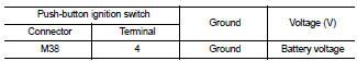
3. Check voltage between push-button ignition switch harness connector and ground.
Is the inspection result normal? YES >> GO TO 4
NO >> GO TO 2
2.CHECK PUSH-BUTTON IGNITION SWITCH CIRCUIT
1. Disconnect BCM harness connector.
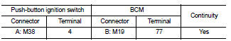
2. Check continuity between push-button ignition switch harness connector M38 (A) terminal 4 and BCM harness connector M19 (B) terminal 77.
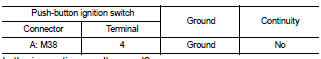
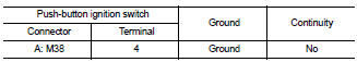
3. Check continuity between push-button ignition switch harness connector M38 (A) terminal 4 and ground.
Is the inspection result normal? YES >> GO TO 3
NO >> Repair harness or connector.
3.CHECK PUSH-BUTTON IGNITION SWITCH
1. Disconnect IPDM E/R harness connector.
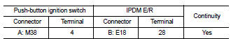
2. Check continuity between push-button ignition switch harness connector M38 (A) terminal 4 and IPDM E/R harness connector E18 (B) terminal 28.
3. Check continuity between push-button ignition switch harness connector and ground.
Is the inspection result normal? YES >> GO TO 4
NO >> Repair harness or connector.
4.CHECK INTERMITTENT INCIDENT
Refer to GI-42, "Intermittent Incident".
>> Inspection End.
 B2619 BCM
 B26e1 no reception of engine status signal