Nissan Altima (L32) 2007-2012 Service Manual: B261A push-button ignition switch
Description
BCM transmits the change in the power supply position with the push-button ignition switch to IPDM E/R via the CAN communication line. IPDM E/R transmits the power supply position status via CAN communication line to BCM.
DTC Logic
DTC DETECTION LOGIC
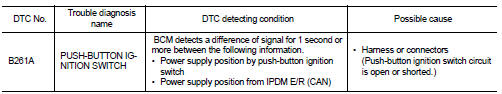
DTC CONFIRMATION PROCEDURE
1. PERFORM DTC CONFIRMATION PROCEDURE
1. Press the push-button ignition switch under the following conditions, and wait for at least 1 second.
- CVT selector lever is in the P or N position.
- Release the brake pedal.
2. Check “Self diagnostic result” with CONSULT-III.
Is DTC detected? YES >> Go to PCS-75, "Diagnosis Procedure".
NO >> Inspection End.
Diagnosis Procedure
1. CHECK PUSH-BUTTON IGNITION SWITCH OPERATION
Press push-button ignition switch and check if it turns to ON.
Does ignition switch turn to ON? YES >> GO TO 2
NO >> GO TO 4
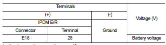
2. CHECK IGNITION SWITCH OUTPUT SIGNAL (IPDM E/R)
1. Disconnect push-button ignition switch.
2. Check voltage between IPDM E/R harness connector and ground.
Is the inspection result normal? YES >> GO TO 3
NO >> Replace IPDM E/R. Refer to PCS-48, "Removal and Installation".
3. CHECK PUSH-BUTTON IGNITION SWITCH CIRCUIT (IPDM E/R)
1. Disconnect IPDM E/R and BCM.
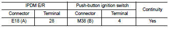
2. Check continuity between IPDM E/R harness connector (A) and push-button ignition switch harness connector (B).
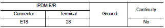
3. Check continuity between IPDM E/R harness connector and ground.
Is the inspection result normal? YES >> GO TO 6
NO >> Repair or replace harness.
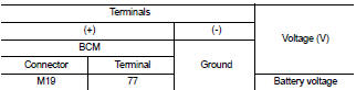
4. CHECK IGNITION SWITCH OUTPUT SIGNAL (BCM)
1. Disconnect push-button ignition switch.
2. Check voltage between BCM harness connector and ground.
Is the inspection result normal? YES >> GO TO 5
NO >> Replace BCM. Refer to BCS-96, "Removal and Installation".
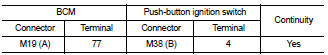
5. CHECK PUSH-BUTTON IGNITION SWITCH CIRCUIT (BCM)
1. Disconnect BCM and IPDM E/R.
2. Check continuity between BCM harness connector (A) and push-button ignition switch harness connector (B).
3. Check continuity between BCM harness connector and ground.
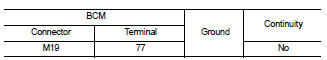
Is the inspection result normal? YES >> GO TO 6
NO >> Repair or replace harness.
6. CHECK INTERMITTENT INCIDENT
Refer to GI-42, "Intermittent Incident".
>> Inspection End.
 B2618 BCM
 Power supply and ground circuit