Nissan Altima (L32) 2007-2012 Service Manual: Basic inspection
DIAGNOSIS AND REPAIR WORKFLOW
Work Flow
OVERALL SEQUENCE
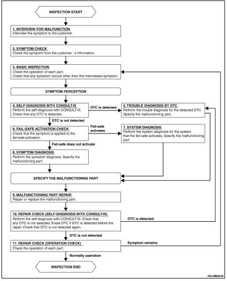
DETAILED FLOW
1.INTERVIEW FOR MALFUNCTION
Find out what the customer's concerns are.
>> GO TO 2
2.SYMPTOM CHECK
Verify the symptom from the customer's information.
>> GO TO 3
3.BASIC INSPECTION
Check the operation of each part. Check that any concerns occur other than those mentioned in the customer interview.
>> GO TO 4
4.SELF-DIAGNOSIS WITH CONSULT-III
Perform the self diagnosis with CONSULT-III. Check that any DTC is detected.
Is any DTC detected? YES >> GO TO 5
NO >> GO TO 6
5.TROUBLE DIAGNOSIS BY DTC
Perform the trouble diagnosis for the detected DTC. Specify the malfunctioning part.
>> GO TO 9
6.FAIL-SAFE ACTIVATION CHECK
Determine if the customer's concern is related to fail-safe activation.
Does the fail-safe activate? YES >> GO TO 7
NO >> GO TO 8
7.SYSTEM DIAGNOSIS
Perform the system diagnosis for the system in which the fail-safe activates. Specify the malfunctioning part.
>> GO TO 9
8.SYMPTOM DIAGNOSIS
Perform the symptom diagnosis. Specify the malfunctioning part.
>> GO TO 9
9.MALFUNCTION PART REPAIR
Repair or replace the malfunctioning part.
>> GO TO 10
10.REPAIR CHECK (SELF-DIAGNOSIS WITH CONSULT-III)
Perform the self diagnosis with CONSULT-III. Verfied that no DTCs are detected. Erase all DTCs detected prior to the repair. Verify that DTC is not detected again.
Is any DTC detected?
YES >> GO TO 5
NO >> GO TO 11
11.REPAIR CHECK (OPERATION CHECK)
Check the operation of each part.
Does it operate normally? YES >> Inspection End.
NO >> GO TO 3
 Exterior lighting system
 Function diagnosis