Nissan Altima (L32) 2007-2012 Service Manual: Camera image signal circuit (rear view camera to
camera control
unit)(coupe)
Description
Rear view camera images are transmitted to the rear view camera control unit
using the camera image signal
circuits.
Diagnosis Procedure
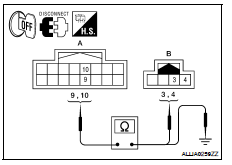
1.CHECK CAMERA IMAGE SIGNAL CIRCUIT CONTINUITY
1. Turn ignition switch OFF.
2. Disconnect rear view camera control unit connector and rear view camera
connector.
3. Check continuity between rear view camera control unit harness
connector B31 (A) terminals 9, 10 and rear view camera harness
connector T7 (B) terminals 3, 4.
4. Check continuity between rear view camera control unit harness
connector B31 (A) terminals 9, 10 and ground.
Is inspection result OK?
YES >> GO TO 2
NO >> Repair harness or connector.
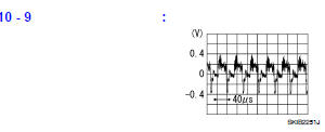
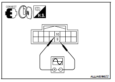
2.CHECK CAMERA IMAGE SIGNAL
1. Connect rear view camera control unit connector and rear view camera
connector.
2. Turn ignition switch ON.
3. Check signal between rear view camera control unit harness
connector B31 terminals 10 and 9.
Is inspection result OK?
YES >> Replace rear view camera control unit. Refer to AV-458, "Removal and
Installation - Coupe".
NO >> Replace rear view camera. Refer to AV-457, "Removal and Installation".
Description
Power is supplied to the microphone from the AV control unit. The microphone
transmits voice signals to the
AV control unit.
Diagnosis Procedure
1.CHECK CONTINUITY BETWEEN AV CONTRO ...
Description
Rear view camera images are transmitted to the rear view camera control unit
using the camera image signal
circuits.
Diagnosis Procedure
1.CHECK CAMERA IMAGE SIGNAL CIRCUIT CONTINU ...


 Microphone signal circuit
 Camera image signal circuit (rear view camera to
camera control
unit)(sedan)
Camera image signal circuit (rear view camera to
camera control
unit)(sedan)