Nissan Altima (L32) 2007-2012 Service Manual: Microphone signal circuit
Description
Power is supplied to the microphone from the AV control unit. The microphone
transmits voice signals to the
AV control unit.
Diagnosis Procedure
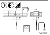
1.CHECK CONTINUITY BETWEEN AV CONTROL UNIT AND MICROPHONE CIRCUIT
1. Turn ignition switch OFF.
2. Disconnect AV control unit connector M46 and microphone connector R7.
3. Check continuity between AV control unit harness connector
M46 (A) terminals 45, 46, 47 and microphone harness connector
R7 (B) terminals 1, 2, 4.
4. Check continuity between AV control unit harness connector
M46 (A) terminals 45, 46, 47 and ground.
Is inspection result OK?
YES >> GO TO 2
NO >> Repair harness or connector.
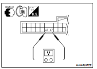
2.CHECK MICROPHONE VCC VOLTAGE
1. Connect AV control unit connector.
2. Turn ignition switch ON.
3. Check voltage between AV control unit harness connector M46
terminals 46 and 47.
Is inspection result OK?
YES >> GO TO 3
NO >> Replace AV control unit. Refer to AV-437, "Removal and
Installation".
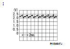
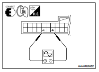
3.CHECK MICROPHONE SIGNAL
1. Connect microphone connector.
2. Check signal between AV control unit harness connector M46
terminals 45 and 47.
Is inspection result OK?
YES >> Replace AV control unit. Refer to AV-437, "Removal and Installation".
NO >> Replace microphone. Refer to AV-456, "Removal and Installation".
Description
When one of the steering wheel audio control switches is pushed, the
resistance in the steering switch circuit
changes depending on which button is pushed.
Diagnosis Procedure
1.CH ...
Description
Rear view camera images are transmitted to the rear view camera control unit
using the camera image signal
circuits.
Diagnosis Procedure
1.CHECK CAMERA IMAGE SIGNAL CIRCUIT CONTINUI ...
Other materials: Moonroof (if so equipped)
Power moonroof
The moonroof will only operate when the
ignition switch is placed in the ON position.
The power moonroof is operational for a
period of time, even if the ignition switch is
placed in the AUTO ACC or OFF position. If
the driver's door or the front passenger's
door is opened during th ...
Warning/Indicator lights
Warning/Indicator light (red)
Brake warning
light
Charge warning
light
Electronic parking
brake indicator
light (if so
equipped)
Engine oil pressure
warning light
Master warning
light
Seat belt warning
light and chime
Security indicator
light
Supplemental air
bag warning light
Warning/Indicator
ligh ...
Rear window and outside mirror
(if so equipped) defroster switch
To defrost the rear window glass and outside
mirrors (if so equipped), place the ignition
switch in the ON position and push the
rear window defroster switch on. The rear
window defroster indicator light on the
switch comes on. Push the switch again to
turn the defroster off.
The rear window defro ...


 Steering switch
 Camera image signal circuit (rear view camera to
camera control
unit)(coupe)
Camera image signal circuit (rear view camera to
camera control
unit)(coupe)