Nissan Altima (L32) 2007-2012 Service Manual: Combination switch reading system
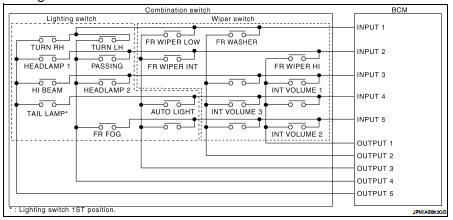
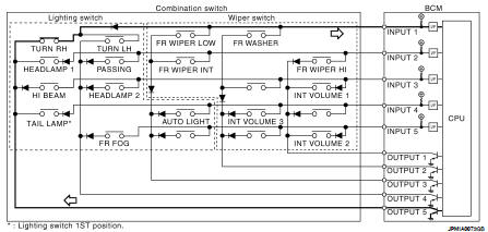
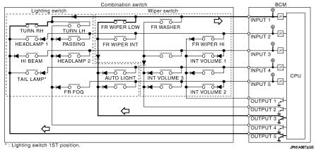
System Diagram
System Description
OUTLINE
• BCM reads the status of the combination switch (light, turn signal, wiper and washer) and recognizes the status of each switch.
• BCM is a combination of 5 output terminals (OUTPUT 1 - 5) and 5 input terminals (INPUT 1 - 5). It reads a maximum of 20 switch status.
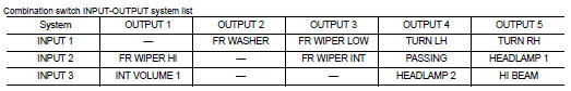
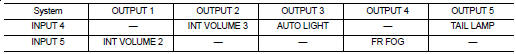
COMBINATION SWITCH MATRIX
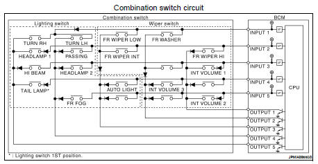
NOTE: Headlamp has a dual system switch.
COMBINATION SWITCH READING FUNCTION
Description
• BCM reads the status of the combination switch at 10ms interval normally.
NOTE: BCM reads the status of the combination switch at 60ms interval when BCM is controlled at low power consumption mode.
• BCM operates as follows and judges the status of the combination switch.
- INPUT 1 - 5 outputs the voltage waveforms of 5 systems simultaneously.
- It operates the transistor on OUTPUT side in the following order: OUTPUT 5 → 4 →3 →2 →1.
- The voltage waveform of INPUT corresponding to the formed circuit changes according to the operation of the transistor on OUTPUT side if any (1 or more) switches are ON.
- It reads this change of the voltage as the status signal of the combination switch.
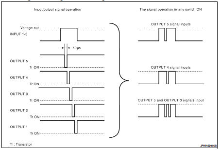
Operation Example
In the following operation example, the combination of the status signals of the combination switch is replaced as follows: INPUT 1 - 5 to “1 - 5” and OUTPUT 1 - 5 to “A - E”.
Example 1: When a switch (TURN RH switch) is turned ON
• The circuit between INPUT 1 and OUTPUT 5 is formed when the TURN RH switch is turned ON.
• BCM detects the combination switch status signal “1E” when the signal of OUTPUT 5 is input to INPUT 1.
• BCM judges that the TURN RH switch is ON when the signal “1E” is detected.
• Example 2: When some switches (TURN RH switch, FR WIPER LOW switch) are turned ON
Example 2: When some switches (turn RH switch, front wiper LO switch) are turned ON
• The circuits between INPUT 1 and OUTPUT 5 and between INPUT 1 and OUTPUT 3 are formed when the TURN RH switch and FR WIPER LOW switch are turned ON.
• BCM detects the combination switch status signal “1CE” when the signals of OUTPUT 3 and OUTPUT 5 are input to INPUT 1.
• BCM judges that the TURN RH switch and FR WIPER LOW switch are ON when the signal “1CE” is detected.
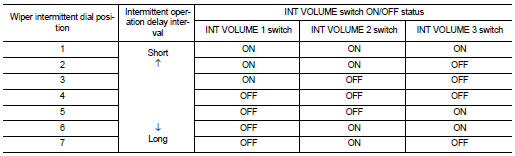
WIPER INTERMITTENT DIAL POSITION SETTING (FRONT WIPER INTERMITTENT OPERATION) BCM judges the wiper intermittent dial 1 - 7 by the status of INT VOLUME 1, 2, and 3 switches.
 Parking, license plate and tail
lamps
Parking, license plate and tail
lamps Diagnosis system (BCM)