Nissan Altima (L32) 2007-2012 Service Manual: Compass
Description
DESCRIPTION
With the ignition switch in the ON position, and the mode (N) switch ON, the compass display will indicate the direction the vehicle is heading.
Vehicle direction is displayed as follows: • N: north
• E: east
• S: south
• W: west
ZONE VARIATION SETTING PROCEDURE
The difference between magnetic north and geographical north can sometimes be great enough to cause false compass readings. This difference is known as variance. In order for the compass to operate properly (accurately) in a particular zone, the zone variation must be calibrated using the following procedure.
Zone Variation Chart
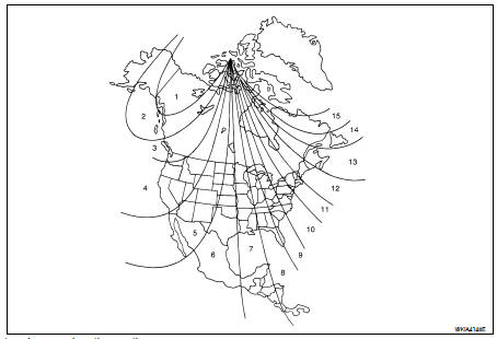
1. Determine your location on the zone map.
2. Turn the ignition switch to the ON position.
3. Press and hold the mode (N) switch for about 5 seconds. The current zone number will appear in the display.
4. Press the mode (N) switch repeatedly until the desired zone number appears in the display.
Once the desired zone number is displayed, stop pressing the mode (N) switch and the display will show a compass direction after a few seconds.
NOTE: Use zone number 5 for Hawaii.
CALIBRATION PROCEDURE
The compass display is equipped with an automatic correction function. If the compass display reads “C” or the direction is not shown correctly, perform the correction procedure below.
1. Press and hold the mode (N) switch for about 9 seconds. The display will read “C”.
2. Drive the vehicle slowly in a circle, in an open, safe place. The initial calibration is completed in about three turns.
NOTE: In places where the terrestrial magnetism is extremely disturbed, the initial correction may start automatically.
 Information display
 Diagnosis system (meter)