Nissan Altima (L32) 2007-2012 Service Manual: Cylinder head
Removal and Installation
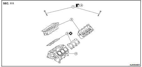
1. Cylinder head bolt
2. Cylinder head
3. Cylinder head gasket
4. Engine block
A. Follow installation procedure
REMOVAL
1. Remove the intake and exhaust camshafts. Refer to EM-177, "Removal and Installation".
2. Remove the coolant outlet housing. Refer to CO-48, "Removal and Installation".
3. Remove the RH and LH cylinder head bolts, with power tool.
• The bolts should be loosened gradually in three stages.
• Loosen the bolts in the numerical order as shown.
4. Remove cylinder heads and gaskets.
• Discard the cylinder head gaskets and use new gaskets for installation.
INSTALLATION
1. Before installing the rear timing chain case, remove the old Silicone RTV Sealant from mating surface using a scraper.
• Also remove old sealant from mating surface of cylinder block.
• Remove the old Silicone RTV Sealant from the bolt hole and thread.
2. Before installing the front cam bracket, remove the old RTV Silicone Sealant from the mating surface using a scraper.
• Do not scratch the mating surface.
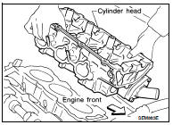
3. Turn the crankshaft until No. 1 piston is set at TDC on the compression stroke.
• The crankshaft key should line up with the right bank cylinder center line as shown.
4. Install new gaskets on the cylinder heads.
CAUTION: Do not rotate crankshaft and camshaft separately or valves will strike piston heads.
5. Inspect the cylinder head bolts before installing the cylinder heads.
CAUTION: Cylinder head bolts are tightened by degree rotation tightening method. Whenever the size difference between d1 and d2 exceeds the limit, replace the bolts with new ones.
Limit (d1 - d2) : 0.11 mm (0.0043 in)
• Lubricate threads and seat surfaces of the bolts with new engine oil.
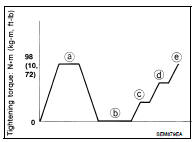
6. Install the cylinder heads on the cylinder block. Tighten the cylinder head bolts in the five steps in the numerical order as shown using Tool.
Tool Number : KV10112100 (BT-8653-A)
• Tightening procedure:
7. Installation of the remaining components is in the reverse order of removal.
Disassembly and Assembly
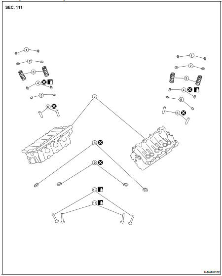
1. Valve collet
2. Valve spring retainer
3. Valve spring
4. Valve oil seal
5. Valve spring seat
6. Valve guide
7. Cylinder head
8. Valve seat (EXH)
9. Valve seat (INT)
10. Valve (EXH)
11. Valve (INT)
CAUTION: • When installing camshafts, chain tensioners, oil seals, or other sliding parts, lubricate contacting surfaces with new engine oil.
• Apply new engine oil to threads and seat surface when installing cylinder head, camshaft sprocket, crankshaft pulley, and camshaft bracket.
• Attach tags to valve lifters so as not to mix them up.
DISASSEMBLY
1. Remove spark plug.
2. Remove valve lifter.
• Identify installation positions, and store them without mixing them up.
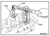
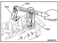
3. Remove valve collet.
• Compress valve spring and remove valve collet with magnet hand using Tool.
CAUTION: When working, take care not to damage valve lifter holes.
4. Remove valve spring retainer, valve spring and valve spring seat.
5. Push valve stem to combustion chamber side, and remove valve.
• Identify installation positions, and store them without mixing them up.
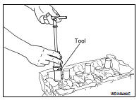
6. Remove valve oil seals using Tool.
Tool number : KV10107902 (J-38959)
7. If valve seat must be replaced, refer to EM-197, "Inspection After Disassembly".
8. If valve guide must be replaced, refer to EM-197, "Inspection After Disassembly".
9. Remove spark plug tube, as necessary.
• Using pair of pliers, pull spark plug tube out of cylinder head.
CAUTION: • Take care not to damage cylinder head.
• Once removed, spark plug tube will be deformed and cannot be reused. Do not remove it unless absolutely necessary.
ASSEMBLY
1. When valve guide is removed, install it. Refer to EM-197, "Inspection After Disassembly".
2. When valve seat is removed, install it. Refer to EM-197, "Inspection After Disassembly".
3. Install valve oil seals using Tool.
Tool number : — (J-39386)

4. Install valve spring seat.
5. Install valves.
• Install it in the original position.
NOTE: Larger diameter valves are for intake side.
6. Install valve spring (uneven pitch type) with narrow pitch end (paint mark) to cylinder head side (valve spring seat side).
7. Install valve spring retainer.
8. Install valve collet.
• Compress valve spring with valve spring compressor, attachment and adapter using Tool. Install valve collet with magnet hand.
CAUTION: When working, take care not to damage valve lifter holes.
• Tap valve stem edge lightly with plastic hammer after installation to check its installed condition.
9. Install valve lifter.
• Install it in the original position.
10. Install spark plug tube.
• Press-fit spark plug tube as follows: a. Remove old liquid gasket adhering to cylinder head mounting hole.
b. Apply sealant to area within approximately 12 mm (0.47 in) from edge of spark plug tube press-fit side.
Use Genuine High Strength Locking Sealant or equivalent. Refer to GI-15, "Recommended Chemical Products and Sealants".
c. Press-fit spark plug tube so that its height (H) is as specified in using suitable drift.
Press-fit height (H) : 37.7 - 38.7 mm (1.484 - 1.529 in)
CAUTION: • When press-fitting, take care not to deform spark plug tube.
• After press-fitting, wipe off liquid gasket protruding onto cylinder-head upper face.
11. Install spark plug.
Inspection After Disassembly
CYLINDER HEAD DISTORTION
Clean the surface of the cylinder head. Use a reliable straightedge and feeler gauge to check the flatness of cylinder head surface.
Check along six positions as shown.
If beyond the specified limit, resurface or replace it.
The limit for cylinder head resurfacing is determined by the cylinder block resurfacing.
After resurfacing cylinder head, check that camshaft rotates freely by hand. If resistance is felt, cylinder head must be replaced.
Nominal cylinder head height : 126.3 - 126.5 mm (4.972 - 4.980 in)
VALVE GUIDE CLEARANCE
1. Measure valve deflection as shown. (Valve and valve guide mostly wear in this direction.)
2. If it exceeds the limit, check valve to valve guide clearance.
a. Measure valve stem diameter and valve guide inner diameter.
Refer to EM-229, "Camshaft".
b. Check that clearance is within specification.
(Valve guide clearance) = (Valve guide inner diameter) - (Valve stem diameter)
c. If it exceeds the limit, replace valve or valve guide.
VALVE GUIDE REPLACEMENT
When valve guide is removed, replace with oversized [0.2 mm (0.008 in)] valve guide.
1. To remove valve guide, heat cylinder head to 110° to 130°C (230° to 266°F) by soaking in heated oil.
2. Drive out the valve guide with a press [under a 20 kN (2.2 US ton) pressure] or hammer and suitable tool.
3. Ream cylinder head valve guide hole.
4. Heat cylinder head to 110° to 130°C (230° to 266°F) by soaking in heated oil and press new valve guide from camshaft side into the cylinder head to the dimensions as shown.
Projection (L) : 12.6 - 12.8 mm (0.496 - 0.504 in)
5. Using a valve guide reamer, apply a reamer finish to the valve guide.

VALVE SEAT CONTACT
• After confirming that the dimensions of valve guides and valves are within specifications, perform this procedure.
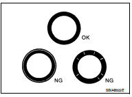
• Apply prussian blue onto contacting surface of valve seat to check the condition of the valve contact on the surface.
• Check if the contact area band is continuous all around the circumference.
• If not, grind to adjust valve fitting and check again. If the contacting surface still has N.G conditions even after the re-check, replace valve seat.
VALVE SEAT REPLACEMENT
1. Bore out old seat until it collapses. Boring should not continue beyond the bottom face of the seat recess in cylinder head. Set the machine depth stop to ensure this.
2. Ream cylinder head recess for service valve seat.
Be sure to ream in circles concentric to the valve guide center.
This will enable valve seat to fit correctly.
3. Heat cylinder head to 110° to 130°C (230° to 266°F) by soaking in heated oil.
4. Press fit valve seat until it seats on the bottom.
5. Cut or grind valve seat using suitable tool to the specified dimensions. Refer to EM-229, "Camshaft".
6. After cutting, lap valve seat with abrasive compound.
7. Check valve seating condition.
8. Use a depth gauge to measure the distance between the mounting surface of the cylinder head spring seat and the valve stem end. If the distance is shorter than specified, repeat step 5 to adjust it. If it is longer, replace the valve seat with a new one.
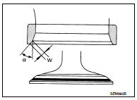
VALVE SPRING SQUARENESS
Set try square along the side of valve spring and rotate the spring.
Measure the maximum clearance between the top face of spring and try square.
Out-of-square limit : Less than 2.0 mm (0.079 in)
VALVE SPRING DIMENSIONS AND VALVE SPRING PRESSURE LOAD
Check valve spring pressure at specified spring height.
If it is not within specifications, replace the spring.
 Oil seal
 Removal and installation